This quick guide covers the Artekit AK-MP3209 Boost Converter board, the basic operating fundamentals, a practical example and instructions on setting a custom output voltage.
Introduction to Boost Converters
A boost converter, or step-up converter, is a switching DC/DC converter that takes a lower voltage on the input, and delivers a higher, fixed voltage on the output. This allows you to power up devices when your voltage source is less than the required operating voltage of the device. A typical example: to power up a 12V device using a 3.7V lithium battery.
The theory of operation of a boost converted can be roughly briefed as a continuous cycle where there is an inductor (a coil) that stores energy from a voltage source, and then this energy is released together with the energy from the source. The cycle repeats and the sum of the voltage from the source plus the stored energy in the inductor results in a fixed output voltage, that is higher than the input voltage.
The S switch represents the electrical switch (a MOSFET, BJT or IGBT transistor in most cases) driven by a PWM signal from the boost converter. When the switch is closed, the inductor stores energy from the source. When the switch is open, the inductor inverts its polarity and releases the stored energy. The energy, delivered as output voltage, is equal to Vin (the source) plus the energy stored by the inductor. At the output, there is a capacitor that smooths the resulting ripple from the PWM and a diode that prevents reverse voltage when the inductor changes its polarity.
The boost converter is constantly checking the output voltage through a feedback pin. An internal Control Logic automatically adjusts the PWM duty cycle according to the desired output voltage and the voltage sensed on the feedback pin. Most modern boost converters have PWM frequencies between 300kHz to 3MHz, and the higher the frequency, the higher the efficiency.
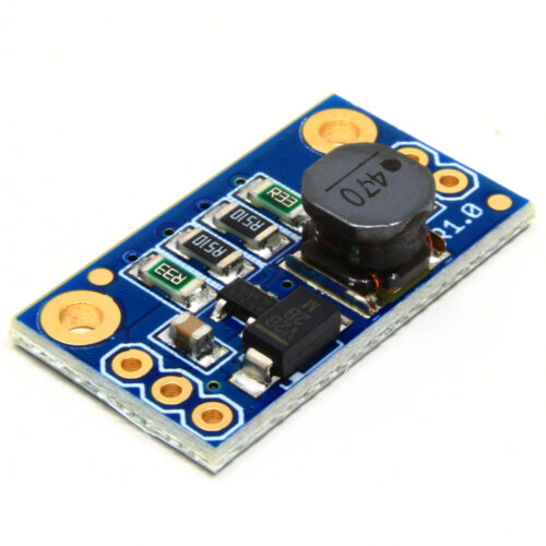
AK-MP3209 – Hardware Overview
The AK-MP3209 is a board based on the MP3209 device from Monolithic Power Systems.
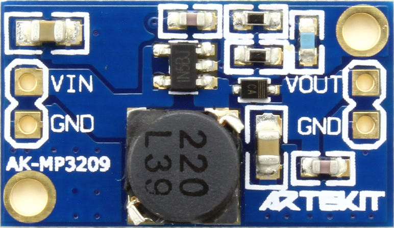
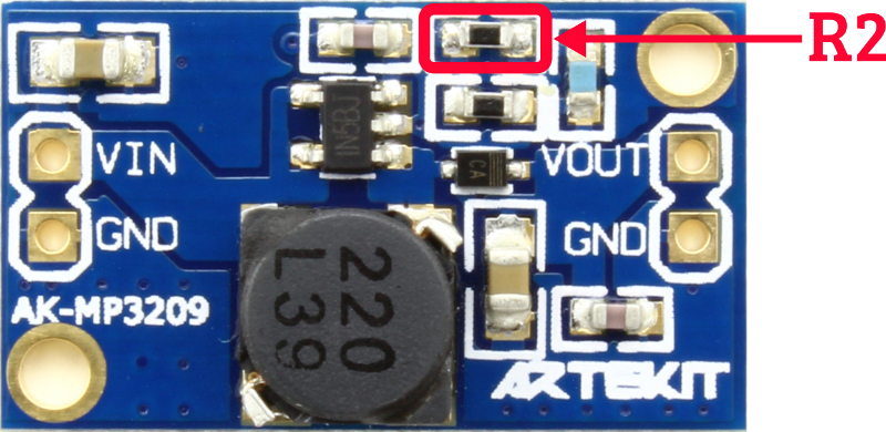
The MP3209 IC is the small 5-pins component right above the inductor. The other components are the voltage divider resistors, the output Schottky diode, the input and output capacitors.
The board comes with factory-set values for two output voltages: 12V or 5V, depending on what you choose at the moment of purchase. A quick guide to configure a custom output voltage can be found at the bottom of this page.
The board has four pins:
VIN is the input from the battery (the lower voltage source).
VOUT is the output, where you connect your circuit. Here you will find 5V or 12V depending on the model.
GND pins for the battery and for the circuit, available on both ends of the board.
The board accepts on VIN voltages from 2.6V up to 5V. The maximum output current (from datasheet) is 350mA, but our tests characterized this board with max. 300mA at 5V and max. 200mA at 12V. Best efficiency is reached with min. ~40mA output load.
A Real Case – Powering Up an Arduino UNO
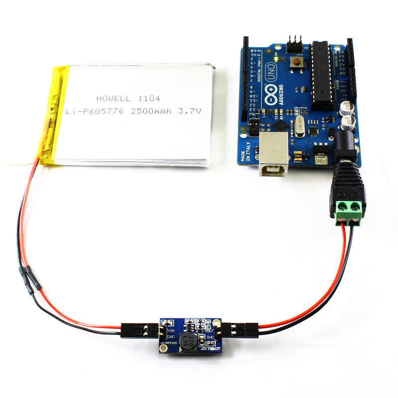
The AK-MP3209 board is extremely easy to use. Just a couple of connections and that’s it.
The 3.7V from a LiPo battery will not be enough to power up a board like an Arduino UNO. You can use a 12V AK-MP3209 board and connect the battery to VIN and GND, then use a Male DC 2.1mm to Screw Terminal Block connector and two wires to connect VOUT and GND to the Arduino. In the picture above we’ve also used some right angle headers and female-female jumper wires to connect everything together.
Little Hack For a Custom Output Voltage
Like many DC/DC converters, the output voltage of the MP3209 depends on a couple of resistor forming a voltage divider. In the AK-MP3209 board these resistors are R1 and R2.
R1 has a fixed value of 510K and must not be changed, but you can affect the resulting output voltage by changing the value of R2.
Locate the R2 resistor in the following picture.
The factory settings are:
R1 = 510K (fixed, do not change)
FB = 1.25V (internal MP3209 feedback voltage).
For the 5V model, R2 = 170K
For the 12V model, R2 = 59.3K
To obtain a different output voltage, change the R2 resistor using the following formula:
[quote style=”boxed”]R2 = (R1 x FB) / (Vout – FB)[/quote]
Where Vout is the desired output voltage. For example, to obtain a 9V regulated output:
[quote style=”boxed”]R2 = (R1 x FB) / (Vout – FB) = (510000 x 1.25) / (9 – 1.25) = 82.26K Ohm.[/quote]
More Info
As usual, a good look at the MP3209 datasheet will give you some more insight about this specific boost converter.