Hello, this is Ivan, and welcome back to another complete project from Artekit.
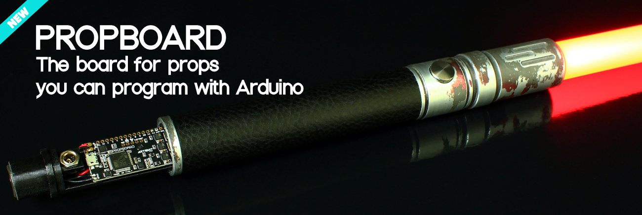
This time we bring you a board that simulates the sounds from a lightsaber, using low cost components. This project is a little more complex than the projects we have done before for the blog, and it will need a few external components. But don’t worry, it’s nothing hard to get.
Side note: If you are looking for a ready-to-go board for a lighsaber project, check out the new PropBoard!
We wanted to do another project before the end of the summer. So as usual, we filled the table with every little piece of hardware we found around the lab. And nothing came out. After a few days, we received the breakout boards batch, and that changed the game. So, between one earthquake and the other, the project took shape.
Enough chat. Let’s see what we are talking about:
What’s on the board?
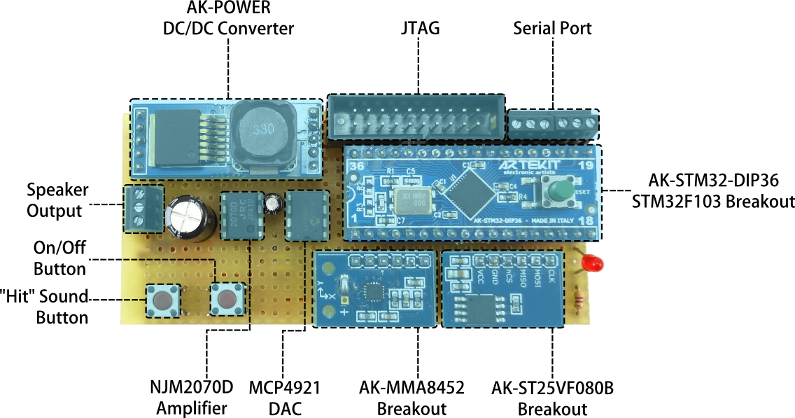
For this demo board we have used:
- A STM32F103T8 Cortex M3 (we use the AK-STM32-DIP36 breakout board).
- A Freescale MMA8452Q accelerometer (we use the AK-MMA8452 breakout board).
- A SST SST25VF080B 8Mbit serial flash (we use the AK-SST25VF080B breakout board).
- A Microchip DAC, the MCP4921.
- A JRC NJM2070D audio amplifier.
- An 8 omh speaker.
- A 9V battery with battery holder.
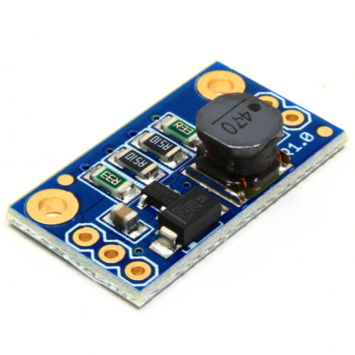
- An AK-POWER to step down the 9V from the battery.
- Resistors: 1 x 47K, 1 x 1 ohm, 10K potentiometer.
- Capacitors: 2 x 100uF/16V Capacitor, 1 x 10nF/16V Capacitor, 1 x 470uF/16V Capacitor.
- A couple of push buttons.
- Optional:
As you can see in the video, we are using a desktop PC speaker, but just for the plastic case around it (there is no amp inside the case). So you can use any 8 ohm, 4W speaker. If you are using a hacked-from-somewhere speaker, we recommend you to find a proper enclosure, until you find a nice pitch. Having the speaker lying on the table only makes low volume noises.
How does this works?
We have the STM32 running the program (source code here), that senses the buttons and processes the accelerometer indications, reads the waveforms from the serial flash and sends them to the DAC, then to the audio amplifier.
Basically we need to detect two events: when the blade hits something and when the blade moves. The MMA8452Q has two interrupt pins that can be set to signal pre-configured events. At startup we tell the accelerometer to detect a “pulse” (a tap) and a transient (that is a certain acceleration in a given window of time). With this two events we can detect when the blade hits something (a pulse) or moves (a transient). We have the transient detection on pin PB1 and the pulse detection on PB2, of the STM32.
Maths are done inside the accelerometer (by Freescale), so the I2C channel is free for whatever you want after the startup. This is a nice feature of the MMA8452Q, that frees resources by processing the most common accelerometer operations inside the IC. Optionally you can query the accelerometer to know on which axis a given event was detected, current acceleration, etc.
Where is the sound coming from?
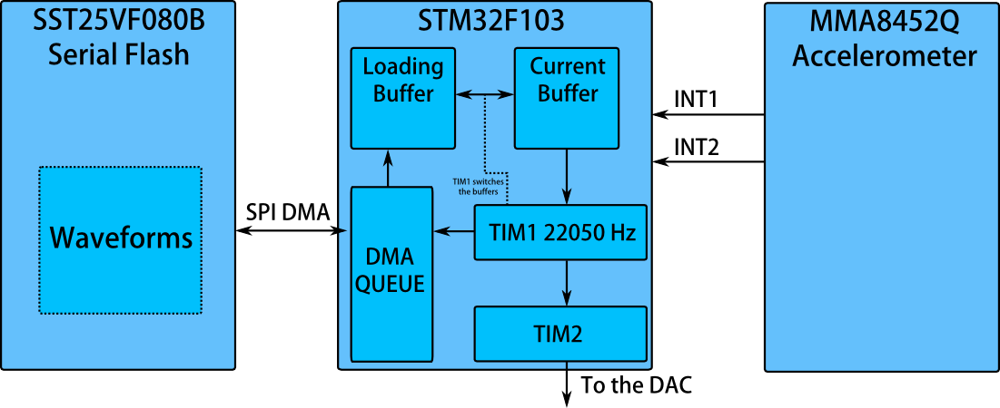
The waveforms are stored inside the SST25VF080B serial flash. In this case we are using 16-Bit WAV files at 22050 KHz sample rate. We have found the sound files at freesound.org, from an user called joe93barlow (thanks to him).
At first we have tried to use PWM and delta-sigma PWM to generate the sound. But at 16-Bit 22050 Hz it needs a very high PWM frequency. It might work with 8000 Hz audio, but we wanted something with a little bit more quality. So we opted for the external DAC (if you are using a high-density or XL-density STM32, those have an integrated DAC).
The DAC we are using is a 12-Bit DAC. So we have to shift the 16-Bit samples down to 12-Bit. This is a limitation by the fact that the MCP4921 was the only non-SMD DAC we’ve found in our lab. A 16-Bit DAC can be used in place of the MCP4921, and they are more or less the same to use.
Here we enter more in detail on the source code: these waveform are logically divided into two sound groups. The HUM sound, and the ALT sounds: the HUM is the background sound that is always on. The ALT are sporadic sounds that are mixed with the HUM sound. These ALT sounds are divided in the following way: the ON sound, the OFF sound, the HIT sound (a laser from a pistol hits the blade), the STRIKE sound (two saber blades that meet) and the SWING (sort of a doppler simulation when the blade is moved quickly). These are the kind of sound we are playing when an event (pulse, transient and buttons) is detected.
TIM1 generates an interrupt at every sample we have to send (at 22050 Hz). The interrupt code fetches a sample and enables TIM2 to send the sample to the DAC.
If you are quick on maths you have noticed we have to send a sample to the DAC every 0.045 ms, and we have to achieve a fluid, constant output without interruptions. Sometimes we have to mix the HUM sound with the ALT sound so we need to read two waveforms instead of one. All this while leaving to the STM32 enough room to do some processing.
Interesting. Tell me more.
The solution was to read chunks of audio samples using a double buffer. While we play a chunk of samples, in the meantime, we quickly read (at 36Mhz from the serial flash) the next chunk of samples. Since we are dealing only with 20KB of RAM, the secret of this project is how fast we can read from the serial flash. If you are not using a SST25VF080B, you will need an equally fast serial flash.
When the first chunk of data is done playing, we quickly switch buffers and start playing the next chunk. The first buffer is free to load another chunk of samples. The cycle repeats. Since we are playing 22050 samples per second, the chunk size has to be long enough to keep playing while we read another chunk.
The said method is done for two kinds of sounds (ALT and HUM), that have to be loaded and mixed in real time. So instead of two switching-buffers, we have four. This sums to the time the chunk has to be playing while we grab (possibly) another two chunks (one for HUM, one for ALT when it’s playing).
So we have TIM1 running at aprox. 22050 Hz, mixing samples. And TIM2 sending the last read (and mixed) sample to the DAC. Since we don’t want to be busy all the time inside a timer interrupt, we use SPI with DMA. There is a “DMA request queue” mechanism defined in dma.c that appends DMA requests for sound chunks and executes them one after another, and flags the chuncks as “ready” when it’s done reading from the serial flash. The serial flash is so fast that I believe we are wasting more time setting the DMA stuff than actually reading.
 The samples are mixed simply by adding the PCM values of the HUM and ALT waveforms. The PCM values for a (signed) 16-Bit audio file go from -32768 up to 32767. If the sum goes beyond that range we clip it at the maximum positive or negative value. There is a lot of discussion out there of how the mixing should be done. We picked that because it sounds decent with our waveforms. If you want to change the algorithm, it is in the MixSamples() function in main.c.
Buttons are simple: one for turning the thing on and off, and one for the HIT sound since we didn’t find a simpler way to simulate a laser pistol shooting at a laser blade we don’t have. 🙂
You can find more insights on the implementation by browsing the source code.
I want to build one.
This is what you need:
Optionally:
The schematics here above uses the AK-MMA8452 V1 board. We actually ship the AK-MMA8452 V2 board and it is necessary to enable the on-board I2C pull-ups and join the ADDR solder jumper in order to make the project compatible with the AK-MMA8452 V1 version.
For uploading the sound files (included in the source code) you have to connect the serial port to the PC (indicated in the schematics, through screw terminals, and it is TTL, so make sure you put a level translator). Connect the serial port and open up a terminal (like TeraTerm) at 115200 bps, 8, N, 1, and press any key. The sound output will stop and you will see the message “Start sending the file. Reset the board when finished.”. Send the “sounds.bin” file, and reset the board when finished. If you are using TeraTerm make sure you click on the “binary” checkbox in the “Open file” dialog before sending the file.
The “sounds.bin” file can be generated using a program included in the package (VS2010 source code available). This is a very (very) simple program that assembles the sound file. Press the “Add file” button and pick a 16-Bit WAV PCM file at 22050 KHz (yes, only in that format) of a given type: HUM, ON, OFF, HIT, STRIKE, SWING. Then select the right type in the combo-box. Just make sure to include only one HUM sound, one ON sound, one OFF sound, and try to add the HIT/STRIKE/SWING types all together (add all the HIT sounds, then all the STRIKE sounds, and so on). With the waveforms ordered that way, the program can select them pseudo-randomly, in order to not repeat the same sounds.
Conclusion
We hope you have enjoyed reading (and implementing) this project as much as we have enjoyed building it. This project also settles the base for all kind of audio projects you can do, like an audio recorder or a generic music player. The code size is quite small (7200 bytes with O3 optimization) so there is plenty of room for you to play and improve the project.
It is known that every initiated into the force has to build his own lightsaber. Well… you can start with this.
Have fun.
The Artekit Team.


113 Responses
Hi I want to build this board over a few months as I can’t afford all of the parts yet so I would just like to ask if you will still have all the parts on your site if I do it over 3 months
Yes. We are not discontinuing these products. There shouldn’t be no stock at that time it should be back in a few days.
hi thanks for the reply i have just one more question i would like to ask, can you provide me with a full schematic, i have seen the one you have but i would like one of all the parts connected together in one big diagram. i am sorry if i have pushed you to much thanks shahin
The schematic is there. I don’t think it would be clearer by not separating individual components and connecting them all together. Just follow net’s names and ask any questions you may have, here or in the forum.
Sweet project! Just a couple of questions though; how do you set the Audio volume? And could you use an SD card instead of your current method?
Cheers!
Thank you.
Volume can be adjusted with the potentiometer (it’s on the back of the board). In the schematics it is named “R3”. By setting it too loud you may distort the sound. It depends also on the speaker you use.
You can use an SD by removing the serial flash and connecting it to the SPI1. You will need a fat file system to access the files (like FatFS http://elm-chan.org/fsw/ff/00index_e.html). There is flash room for that, and examples on implementation can be found for STM32.
Have you tried using it, because when i tried with fat fs, sound is kind of interrupted.
No, but I think it can be achieved by increasing buffers size. A high speed SD and a better implementation of the DMA logic could help.
quick question, do you send shipments overseas? (specifically to guadalajara, mexico)
Hi.
Yes, we ship overseas. More details here: http://www.artekit.eu/delivery-and-payment/
I am trying to do something similar with an arduino Uno, and I am having trouble finding the “source code” in the format that I am used to using in the zip file. can you point me in the right direction or am I missing something entirely
Hi,
this is a project for KEIL uVision or Eclipse, for an ARM Cortex M3. It won’t work on an Arduino UNO or its IDE.
Hi there!
I need to know if you can sell me the entire kit assembled and programmed and how many EUR can be. Many thanks.
Hello,
We’ve built this as a demo project and for fun. I’m sorry, but we cannot sell it or assemble more.
Ciao a tutti, sono un appassionato della saga e ovviamente sono interessato al progetto.
Da quello che ho capito avete fatto un demo che non può essere venduto, neanche a chi come me è incapace di assemblare tutti questi componenti.
La mia domanda è questa, è possibile avere tutte queste belle spiegazioni, link vari, descrizioni dei componenti in italiano?
Già faccio molta fatica nell’elettronica in più è in inglese…lingua a me non molto congeniale.
Vi ringrazio anticipatamente per la Vostra disponibilità
Saluti
Andrea
Ciao Andrea,
Tempo permettendo apriremo una sezione in Italiano. Per adesso abbiamo questo qui in inglese, cosi in altri paesi lo possono capire.
Se hai dubbi o domande sul progetto, possiamo aiutarti (meglio sul forum) entro i nostri limiti.
I cant seem to find the JTAG, Serial port, or speaker output on you site. If you do have them could you please tell me where I could find them.
Hi,
A JTAG could be the AK-Link JTAG, for the serial port, an AK-RS232 level converter should be OK. The speaker, we don’t sell those yet.
Hello Artekit.
You could not attach a phlegm drawing , he would be a powerful help .
Thank you in advance.
Sorry, what is a phlegm drawing?
Hello Ivan.
I am sorry a bit the English is going hardly .
Printed circuit boards.
I thought of a this
http://webpages.csus.edu/~heinega/TWO_CAMERA_3D_SYNC_BOARD-circuit_board-bw-sl-trace_only-Lg_Pads.jpg
Hi. Since it’s mounted on a protoboard it has not a precise printed circuit drawing.
Hello,
Long time since Anyone posted somehing here,
I’m building à binch of different lightsabers.
It started with me buying à cheap fake one and now i’m filming à lightsaber battle scène and building all kinds of Sabers.
I’m used to gettin my soundboard’s out of older lightsabers, because The soundboardS on THE sabershop are just to expensive.
But than i found this website and after looking up THE parts i could Find that you use, i was suprised how cheap it is.
Zo my questipn is; Can you five me à list of all THE parts jat i meed to buld à proper light, soundboard?
Great website!
Mickey
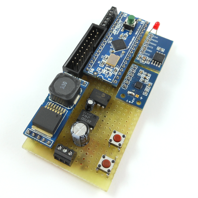
Hi do you have any photos of how this looks on the bottom of the breadboard
Hi, I wasn’t sure what the output and other specs of the AK-POWER was. There are several options, and I wasn’t sure what I should order.
Neat board!
Julia
Hi Julia.
Thank you. If you’ve ordered a 3.3V AK-POWER board, you should be OK.
OK, thank you!
Sorry, one more question.
What would be the maximum amount of voltage/Farads I could have for the 10nF 16V capacitor?
(as in would it be possible to have a through-hole capacitor with slightly more volts or farads. The one I got was incredibly tiny and I’m not sure how to mount it to a breadboard.)
Hi Julia, sorry for the delay.
It’s a filtering capacitor for the DAC. A higher value will cut high frequency sounds. If you can, try several until you get the desired audio. A cap higher or equal 10V is OK.
We have some capacitors in the shop: http://www.artekit.eu/products/components/discrete/ceramic-capacitors-20-50v-pack-of-10/
Awesome! Thanks!
hi, I did see that the AK-STM32-DIP36 is able to produce pwm signals. I was wondering if any of the pins that can be configured for wmp signals are still available after building this project? and if so, how many?
i’m hoping to use them to drive a LED signal or 2.
Thank you and great job on this project!
I’m hoping to build this project and take it a bit further. are there any free pins available with this build that are capable of producing a PWM signal?
i’m hoping there are at least 2 PWM pins i can use to drive a NPN transistor, which will drive high power LEDs. one PWM pin would be the main LED and will have a flicker in sync with the hum sound. the 2nd signal will flash with the hit and strike sounds. if there are 3 pins available for pwm i can incorporate RGB color mixing.
Hi.
Looking at the schematics (http://www.artekit.eu/resources/blog/Lightsaber/Lightsaber.pdf) I see PA0, PA11 and PA8 pins connected to TIM2_CH1, TIM1_CH4 and TIM1_CH1 respectively. You could use those pins if the frequency of those timers (~22KHz and 2MHz) fit your need.
ive been doing some more research into the cortex-m3’s capabilities and looking at more possible breakout boards. i came across a breakout board that can control 12 channels of 16bit pwm. it uses a SPI interface, and there arent any SPI interfaces available. how difficult would it be (for the coding) to substitute the SPI DAC for a I2C-interface DAC? that would free up a SPI channel for using the PWM module i found, allowing this build to drive main blade LEDs, and also have plenty of hookups for additional accent LEDs. additionally, can the cortex-M3 handle the added PWM channels without losing the flawless audio playback you designed in this project?
i also want to add that i am still taking baby steps with coding. i took an into to C programming course while getting my electronics degree, but that was over 2 years ago. where would be a good place to start on learning how to configure the I2C DAC and adjust the code to send the right signal to it?
Hi,
The DAC is driven by a bit-banged (simulated) SPI, from TIM2. The real available SPI is used to read chunks of audio from the memory. And I wouldn’t change the reading SPI configuration, in order to avoid interruptions in the audio.
A back-of-the-envelope calculation tells me that for a 12-bit audio at 22050 Hz the DAC should process ~44000 bytes/s (16 bits per sample, leaving out the address and other settings from the calculation). A full-speed I2C at 400Kbits can transmit ~50000 bytes/s leaving very little margin. Perhaps you can use a PWM LED controller through I2C (instead of a DAC).
In any case, I cannot quantify how much code intervention it should take.
Hello, i just wanted to know if it is possible to substitute the serial hook up for USB and how might i go about accomplishing that
Hi. The easiest way is by using some usb-to-uart converter like FTDI’s. No code changes are needed for that.
I was curious .. Would it be difficult to change the power source from a 9v to a recharge pack? Or would that change a great deal into schematics?
Hi. Anything between 8V and 30V DC can be used as the power supply, connected to the AK-POWER2500 as in the original schematics. Or you can remove the AK-POWER2500 board and supply 3.3V directly.
What voltage is this ‘recharge pack’?
Hello,
This is all Chinese for me but I have a friend who is into electronics and he said he can program these as well. My only problem is that I need to order the parts and give them to him. I found a lot of components enlisted but I’m not quite sure I covered everything or that I need all these. I read that you do not sell this built together and programmed, but is there a full list what to order for complete build? Thank you for your help.
Hi,
There are some items we sell, like the breakout boards, and others we don’t.
Except for the protoboard, all the required components are listed, and the items we have in store are linked. There is a list also in the schematics (http://www.artekit.eu/resources/blog/Lightsaber/Lightsaber.pdf).
Ok. I saw the schematics earlier just didn’t know what to do with it. It is best if I show this to my friend.
Thank you for your help.
Hey!
I didn’t find the JRC NJM2070D audio amplifier, so what can I substitue it with? Otherwise can I use different breakout boards (what kind?)
Thank you!
Gaspar
Hi,
You need at least a mono amplifier that supports 3.3V. Perhaps some from the TPA*** line of Texas Instruments. The circuit should be adapted to it, though.
We have a mono amplifier board (http://www.artekit.eu/products/accessories/ak-ncs2211-mono-power-amplifier-breakout/) that should work ok with this project.
Hi, finally have alost all I need to get this project under way my only issue is what is the wattage of the resistors in the parts list (ie: .25w, .5w, 1w)
Hi,
Any from 1/8W and above should be OK.
Hi. Please help! How do all the parts connect to one another in the schematic?
For this project here we used wires, solder (and patience).
Yea I know, but I dont know which part to connect to which one.
Hi. Follow the connection name in the schematics. For example, for the connection named “INT1”, connect the pin 16 of the AK-STM32-DIP36 board to the pin 2 of the AK-MMA8452 board
Oh. I see. Thanks alot. This is a great project!!!
And I have another question. What are the labels with the arrows and thar read things like… +VBAT and +3.3V and the ones with the three lines.
And how can I connect a LED to this audio board. The LED just has to go on when everything else goes on and it has to go off when everything else goes of. It does not need to flicker or flash or anything.
Hi,
+VBAT=positive from battery
+3.3V=output of the AK-POWER2500 board.
“three lines”=ground?
This project, as is, does not drive a LED. You’ll have to add a special circuitry to drive a high power LED, if this is what you mean.
Ok, but is there any place where I can connect a high powerd LED driver then?
And the “three lines” are the ones that are almost shaped like an arrow. There is one at the negative pole of the battery and one at the buttons and at lots of other places.
Hi,
I doesn’t come to mind a signal that switches on and off that you can use to turn the LED on/off .
There are some free pins (PA0, PA11 and PA8 pins) you can use to enable the LED, but you’ll have to modify the code. Power supply for the LED, depends on what you want to use. On the board there is 9V from the battery and 3.3V after the power supply.
Three lines=this? (https://www.google.it/search?q=electrical+ground+symbol)
So I’ve decided to try a 16-dac and went with the ADS1115 16-Bit problem is I’m having issues with where to connect it on the main board any suggestions?
Hi,
specifically, which issues?
Also, 22kHz audio on a 400kHz I2C , I don’t know if it will work. Read http://www.artekit.eu/diy-lightsaber-audio-board/#comment-6655
Ok. Thank you. So the ground wires…dot they just all connect to one another?
And how am I supposed to upload the sound onto the serial flash. Do I just transfer the .zip folder?
And sorry for all the Questions.
Hi,
Ground: yes, all together.
Files: read the paragraph starting with “For uploading the sound files…”
Hi. What version of the AK-POWER2500 – DC/DC Converter are you using?
I assume its the AK-POWER-2.5.
Hi. It’s the AK-POWER 3.3V output version.
Thanks. Then 1 last question. In the schematics by the audio amplifier, there is a capacitor labled ‘C5’ but it is not listed in the Bill of Materials. Should I still put it in or not?
Hi. Yes, even if it is missing in the BOM list it should be included.
can I buy the complete working board (without speakers) and how much it costs?
Hello Stefan,
we don’t sell or assemble the board. Sorry.
Hi There
where can i plug in the LED for my blade? at the red 3mm LED one?
or what is the best way to add a blade LED?
thanks
Hello. I’ve used the 3mm LED to know when the board was powered up, so I think it’s not the best place to put your LED.
I think the best way could be to modify the code to produce a signal in any of the remaining free pins to turn the LED on. You’ll need the circuitry to drive the LED too, if it is a high-power one.
How do you program this board?
Hi, you can program it with a JTAG.
I see that the accelerometer is out of stock.
If i use AK-MMA8452 3-Axis Accelerometer Breakout V2 there is any modification in the circuit or software?
Hi. The V2 is the same board but in a different layout. So it’s hardware and software compatible. No need for modifications.
Hi Ivan,
the program hangs in i2c.c line 72 in the while loop:
while(!I2C_CheckEvent(I2C1, I2C_EVENT_MASTER_TRANSMITTER_MODE_SELECTED));
I2C_CheckEvent always returns ERROR, so execution is trapped in this while loop.
The rest works – if I comment out the accelerometer initialization accInit(); in main.c everything works: I hear the hum sound and the hit sounds works too.
I just cannot get the accelerometer running. I am using the V2 version. Any ideas?
What about the bridge between pins 7 and 8 on the schematics? There are no such pins on the V2 board …
Thanks in advance
Michael
Hi Michael,
The V2 accelerometer board has a pull-up on the SA0 pin (address selection). This makes the accelerometer addressable as 0x1D. Try joining the ADDR solder jumper on the accelerometer board or change the #define MMA8452_ADDR 0x1C line in mma8452.c file to #define MMA8452_ADDR 0x1D.
Remember also to enable the pull-ups by soldering the solder jumpers on the back of the accelerometer board.
We can keep this conversation in the forum if you want. There we don’t have the posts nesting as with the comment sections, and it should be clearer.
Hi Ivan,
great, that worked out!
Now comes the real hard part: to squeeze the circuit, the speaker and the batteries into the housing 🙂
Thanks for this fine project!
Michael
Hello,
I have tried to build this project exactly to your schematic. I am using the AK-LINK JTAG, however, I do not know how to connect to it in uVision. Do you have any instructions on how to upload the code?
Thank you!
-Ron
Hi,
The AK-LINK doesn’t work with KEIL but with tools like OpenOCD.
The example here also contains project files for Eclipse + GCC, that can be used together with OpenOCD to develop, download and debug code.
Another possibility is to download the binary file with the STM32 Flash Demostrator (http://www.st.com/web/en/catalog/tools/PF257525) tool, using a serial port and the embedded bootloader in the STM32 (http://www.st.com/web/en/resource/technical/document/application_note/CD00167594.pdf)
Hi! Is there any way to modify this so that an LED would light up as well? I want to put this + an LED into a hilt and try to build a saber
Hi,
As is, there is no signal that switches on and off that you can use to drive the LED..
With proper code modifications you can do some PWM to drive the LED on one of the free pins.
This explanation did not fully understand . How can I install programs on this project and audio files using the JTAG bus with S Link V2. I ‘m so glad you detailed explanation. keil.v5 installed on the PC . Are Keil explains with adjustments ? Please. I do not know the exact English. I use Google translation. I’m sorry if the translation error . Greetings.
RXD , TXD bus to the MAX3232 RS232 Serial Port To TTL Converter Module connecting Keil, I tried to do with Tera Term . But I could not. Help please
Hi!
Please open a thread in the support forum and explain in detail what the problem is and what you have tried until now.
Hi!
“For uploading the sound files (included in the source code) you have to connect the serial port to the PC (indicated in the schematics, through screw terminals, and it is TTL, so make sure you put a level translator). Connect the serial port and open up a terminal (like TeraTerm) at 115200 bps, 8, N, 1, and press any key. The sound output will stop and you will see the message “Start sending the file. Reset the board when finished.”. Send the “sounds.bin” file, and reset the board when finished. If you are using TeraTerm make sure you click on the “binary” checkbox in the “Open file” dialog before sending the file.”
I’m not sure this is mentioned ones. I need more descriptive information. UART RX and TX bus TTL RS232 converter using a lightsaber could transfer your project SMT32F103 motherboard. I need to RS232 converter and a PC cable connection pin number.
I’m having difficulty in a statement. Please try to understand and help me.
I’ll try this if JTAG. I will use ST-Link V2 Debug.
Greetings.
Hi, for support please use the forum. Thanks.
Hi, I’ve built the board and I’ve tried to upload the sound file. I used Tera Term with a USB connection on port COM7. I configured the port at 115200 bps, 8, N, 1 and when I send the file I see the file get charged but only if the checkbox Binary is not checked, otherwise nothing happen. In any case the board don’t work. I have to change some configuration because I use a USB port? Please help me. Many thanks.
Hi. You need to send the file with the binary option checked. Please go to the support forum and explain there how you connected the board and what you have done until now.
Just built this, it works!
I was not able to make the supplied Eclipse project work with the latest version of the GNU ARM Eclipse Toolchain. I builds without errors, but no ELF file is produced (last few steps in the tool chain was not run). I had to create a new empty STM32F103T8 project and then add your code files manually to make it build.
I also had some problems with the code immediately entering the sound file download/flash program procedure when I did not have the serial/UART cable connected to the PC (noise on RX pin?). After uploading the sounds.bin and then removing the configPoll() call in the main loop it works OK.
Thanks for a cool project, I learned a lot from building it!
Hi frodesto, Thank you for commenting, and sorry for the delayed answer.
Yes, a noisy UART RX pin can be interpreted as the user sending a character. A weak pull-up or pull-down resistor (external or internal) can solve the problem.
Hi, I try to use your SndPack application to pack some new sounds. However some files just can’t be included, though they have the same attributes (.wav 352kbps). Even a same wav file re-saved by Adobe Audition can’t be included.
Do you know why? Many thanks
Hi,
You have to be sure they are mono, sample rate 22050 Hz and 16-bit per sample.
352kbps doesn’t say much about the file format.
Many thanks for your reply. yes I am sure these parameters are the same (sample rate 22050 Hz and 16-bit per sample). The problem is that I can choose these new files to add into the bin, yet some of them is ok, while the rest just don’t have any response. My OS is win7 home edition. I use this software in XP compatible mode
Ciao Ivan,
Stavo studiando il progetto sotto alcuni aspetti pratici/costruttivi, quando ho realizzato che il mio pc non ha la rs 232.
Oltre che cercare un computer con la porta.per fare il trasferimento, esistono altre alternativa?
Come posso fare?
Ciao,
Il progetto allo stato attuale non contempla alternative diverse dalla porta seriale, ma potresti:
a. Trovare un PC con una porta seriale, come hai detto tu.
b. Dato che ci sono i sorgenti a disposizione, generare un metodo per trasferire il file con protocollo e/o interfaccia diversa.
c. Usare un adattatore USB-to-Serial.
Grazie mille.
Ciao Ivan,
sto cercando gli altri componenti e riguardo il MCP4921 ne ho trovato 2 tipi:
-E/P
-E/MS
Quale mi serve?
Grazie
– DAC MCP4921-E/SN 12 bit-Bit, SOIC, Seriale (SPI/Microwire), 8 Pin
– DAC MCP4921-E/P 12 bit-Bit, PDIP, Seriale (SPI/Microwire), 8 Pin
– DAC MCP4921-E/MS 12 bit-Bit, MSOP SPI, 8 Pin
Quelle ultime lettere dovrebbero essere il packaging (che puoi verificare con il datasheet). In quel caso, va bene qualsiasi a 8 pin. Il progetto originale usa il MCP4921-E/P (8 pin PDIP).
OK Grazie!
Lo speaker emette suoni tipo “fuori sintonia” delle vecchie radio a onde corte. Come faccio a verificare l’avvenuto trasferimento del file? Considera che sto utilizzando un cavo usb/rs232.
Così posso discriminare l’errore, se di assemblaggio della scheda o di trasferimento dei dati.
Attualmente non c’e un checksum per verificare il trasferimento, ma viene comunque fatta una semplice verifica nella funzione configLoad().
Se il rumore lo senti appena dai alimentazione, direi che non e’ un problema di trasferimento dati. Se invece senti rumore quando premi il tasto di accensione, potrebbero essere i dati o assemblaggio. Direi di fare qualche verifica con JTAG e vedere se quello che viene inviato al DAC sia coerente con i dati dei file audio.
I rumori li sento appena do alimentazione. Quando premo il pulsante di accenzione invece, resta muto. Il JTAG lo davi per opzionale e per questioni di spazio non l’ho montato. Non ho le capacità/conoscenze/attrezzature per le verifiche che proponei.
Ciao,
Il JTAG serve a programmare il micro. Una volta programmato puoi toglierlo, ma a meno che non usi altri metodi, il JTAG serve per fare la prima programmazione e anche per debuggare. Come hai fatto a programmare il micro?
Purtroppo se non hai le attrezzature e conoscenze minime c’e poco che possiamo fare da qui come supporto. Possiamo cercare di aiutarti il più possibile, ma Il progetto prevede conoscenze minime in elettronica, programmazione e risoluzione di problemi.
In ogni caso, proseguiamo via email ([email protected]).
Hey, It seems this project is still supported, is there any chance that links will be added to the other parts? I’m having trouble finding some of the parts written here, I would really appreciate it!
Also, I’m a software developer but I did not study any electrical engineering, would this kind of project be too hard for a novice EE learner?
I saw boards that do similar things that price about 70$, but I thought making one on my own might be cheaper and more fun =]
Thanks a lot for any answer, and sorry for the bother =O
Hello. Sorry for the late answer.
Most of the missing parts can be found on big distributors like Mouser or Digikey.
This is not the easiest project but it’s not that hard. My advise: to have the right instrumentation (oscilloscope, multimeter) to diagnose if something doesn’t work, and some code debug capabilities and tools (JTAG for example).
Hi is there any chance I can purchase a completed board from you guys so all I have to do is fit it to my hilt? I’m building a Lord Revan sabre from scratch and I have never done any electronics work. Plus I’m in the U.K. How much will it cost all together with delivery thanks.
Hi, we don’t sell or assemble the board.
Sorry will the board fit in a tube 2.5cm bore.
Hi, size depends on how you assemble the parts. Dimensions for the boards are available on every product page.
Hello,
Is there a chance that I can add my own sounds? I would like to be able to implement original sound effects that isn’t from a lightsaber, but still keep all the sensibility functions.
Thanks.