Artekit AK-FT232RL Breakout
Learn about the Artekit AK-FT232RL Breakout board, it's pin description, dimensions and usage.
Introduction
This guide is about the Artekit AK-FT232RL Breakout board. We are going to learn all the details about the hardware, software and usage.
What this board does is to convert USB to UART signals allowing you to connect, for example, your PC/MAC to any other board that has an UART with TTL signals.
Suggested reading: The AK-3232 usage guide, and Why do I need a RS232 Level Converter?
The board is built around the well-known FTDI FT232RL IC, the most used and reliable USB-to-Serial converter, with support for many platforms and operating systems.
Beyond the basic USB-to-Serial conversion, the board has a switch that allows you to select the operating voltage: you can choose to work with 3.3V or 5V signals. That is, if the board you are connecting works only with 3.3V or 5V signals, you can safely use it with this breakout board.
The board also has the pinout needed to program Arduino Pro Mini boards, and on the top of the board there are two LEDs that allows you to see the TX and RX signals activity.
The hardware
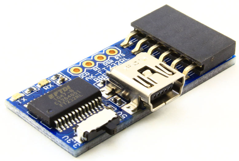
The following picture shows the signals you can find in the connector. The AK-FT232RL Breakout has all the signals available for a full serial port.
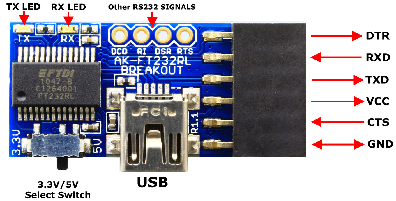
The board has mainly two, 1” (2.54mm) pin pitch connectors: the main black connector you can see at the right with DTR, RXD, TXD, VCC, CTS, and GND signals (arranged in a way to allows you to program Arduino Pro Mini boards), and a four-pin connector on the top, with the remaining serial signals (DCD, RI, DSR and RTS).
On the back of the board you can identify every signal of the main connector, indicated by labels.
You may notice there are 1” (2.54mm) pins underneath the main black connector. These pins are available if you want to use another type of connector, for example right-angle pin headers. You can de-solder the main connector and use any connector you require.
On the USB connector is where you will be connecting your host with an USB mini cable. Usually the host is a PC/MAC but can be also, for example, a Raspberry Pi. The host will will power the board through the cable, so there is no need for an external, separated power supply.
The 3.3V/5V Select Switch can be used to select the output and input levels of the signals, including the voltage output by the VCC pin. It’s advisable to use this switch while the board is disconnected from the PC/MAC.
The board can drive an output current up to 500mA in 5V mode, limited by the USB Host, and <50mA in 3.3V mode.
The software
This USB-to-Serial converter needs drivers. On modern operating systems (Linux, Windows 7 and up, OSX) the drivers should be already installed, or will be downloaded automatically when you plug the board in for the first time.
In the case you still need to manually install the drivers, you can find them in this link.
There are two kind of drivers: VCP drivers for Virtual COM Port emulation (this is the most commonly used and the one that is automatically installed) and D2XX that allows you to access the USB-to-Serial converter through a special DLL for advanced usage.
We recommend the VCP drivers that will quickly allow you to use the board with programs like TeraTerm or PuTTY.
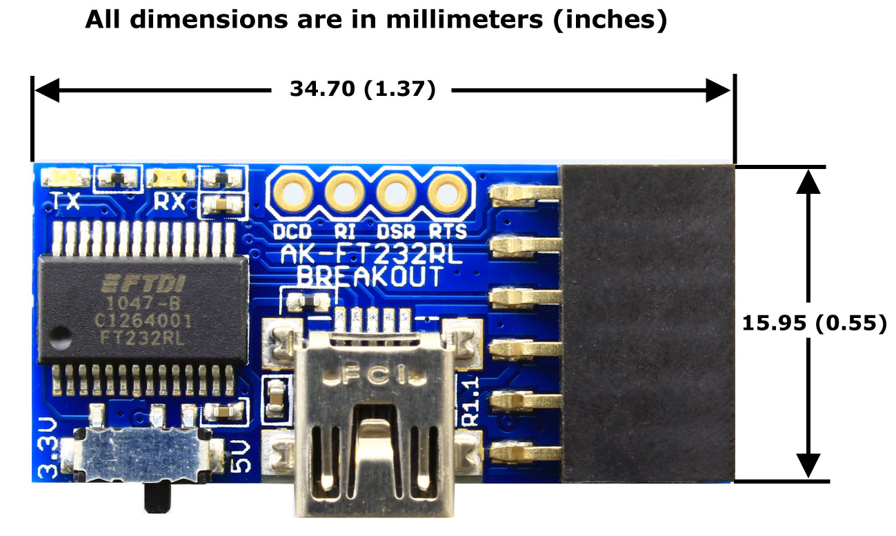
Board dimensions