Artekit AK-TXS0108 and AK-TXB0108
Reference manual for the Artekit AK-TXS0108 and AK-TXB0108.
Introduction
The Artekit AK-TXS0108 and AK-TXB0108 breakout boards convert digital signals from a lower voltage (for example 3.3V) to a higher voltage (like 5V) and back. It’s perfect for converting communication buses with different voltage requirements like, for example, a 3.3V Raspberry PI and a 5V sensor, or for converting 5V Arduino IO signals into 3.3V signals.
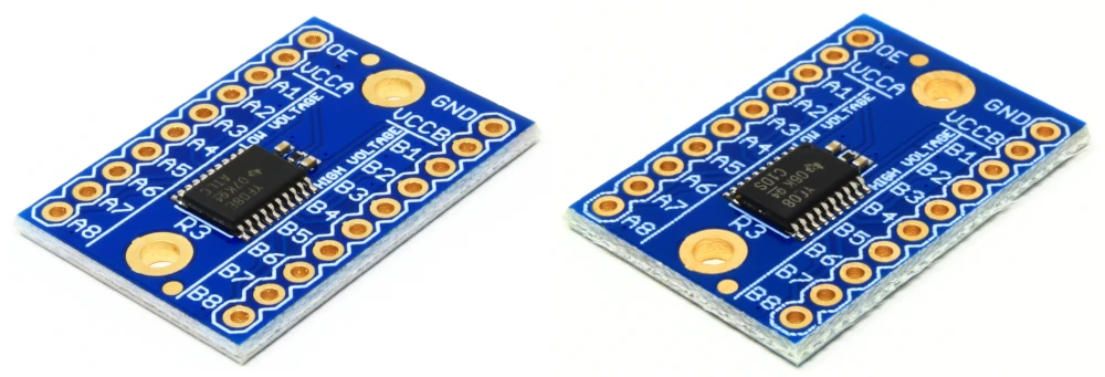
Artekit Labs AK-TXS0108 and AK-TXB0108.
The AK-TXS0108 and AK-TXB0108 are based on the Texas Instruments TXS0108 and TXB0108 IC and provide 8 bidirectional logic level converters in a single board.
Features
- Eight level converters in a single board.
- Bidirectional: no control signal needed.
- AK-TXB0108: optimized for open-drain signals.
- AK-TXS0108: optimized for push-pull signals.
- Converts signals from 1.2V-3.6V range into 1.65V-5.5V range and vice versa.
- Output enable pin.
- Built-in ESD protection of +/-15 kV.
- Compact form factor.
- Mounting holes.
- Easy to use.
AK-TXS0108 and AK-TXB0108: differences
Both the AK-TXS0108 and AK-TXB0108 share common features:
Bidirectional Logic Level Conversion: These boards allow seamless signal translation from a lower voltage (e.g., 3.3V) to a higher voltage (e.g., 5V) and vice versa.
Automatic Direction Control: No predefined inputs or outputs—pins dynamically switch between input and output as needed.
AK-TXS0108
Ideal for open-drain buses like I2C and 1-Wire, but can be used with other digital signals like SPI and UART.
Compatibility: Supports both push-pull and open-drain I/Os.
Data Rate: Capable of handling data rates up to 110 Mbps.
AK-TXB0108
Push-Pull Only: The AK-TXB0108 is designed exclusively for push-pull signals. Recommended for buses like SPI, UART, etc.
Compatibility: Limited to push-pull signals; not suitable for open-drain requirements.
Data Rate: Supports data rates up to 20 Mbps.
Usage
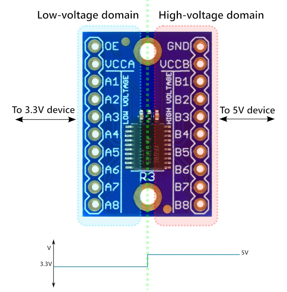
As you can see in the above picture, the board can figuratively be “split” in a half vertically. On the left side there is the “low voltage domain”, accepting signals in the 1.2V-3.6V range. On the right side there is the “high voltage domain”, accepting signals in the 1.65V-5.5V range.
The board has 8 pins named “A” (A1-A8) and eight pins named “B” (B1-B8). There are the pins where the signals to be converted are connected. The signal connected to, for example, A1 will be converted and output to B1 and vice versa.
The VCCA pin has to be connected to the reference voltage for the low voltage domain (for example 3.3V) and the VCCB pin to the reference voltage for the high voltage domain (for example 5V).
The GND pin has to be connected to a common ground between the low and high voltage domains.
The OE pin can be used to disable the level converter and put all the signals into high-impedance state. Connect OE to GND to disable the converter. The usage of this pin is optional and, if left unconnected, the AK-TXS0108 or AK-TXB0108 is always enabled.
Example
In the following example we will connect a typical 5V system (an Arduino UNO board) to a 3.3V I2C sensor using an AK-TXS0108 board.
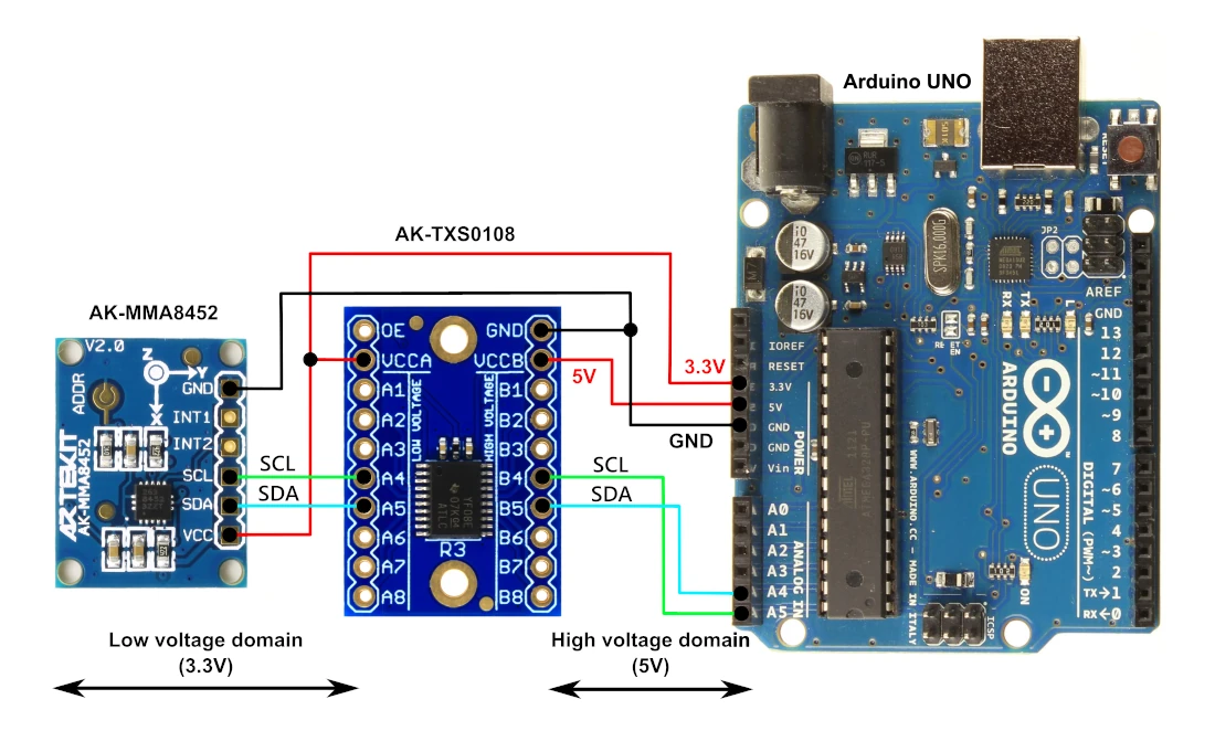
The VCCA pin receives from the Arduino UNO the 3.3V reference voltage for the low voltage domain. The same 3.3V line is also used to provide 3.3V to the sensor.
The VCCB pin receives 5V (also from the Arduino UNO) as the reference voltage for the high voltage domain.
The 3.3V I2C signals (SDA, SCL) of the sensor are connected to the pins A4 and A5, and the 5V I2C signals of the Arduino UNO are connected to the B4 and B5 pins.
This way, the I2C signals coming from the 5V Arduino UNO will be converted into 3.3V signals and vice versa.