Artekit PropBoard Manual
Everything you need to know about the Artekit PropBoard.
Introduction
The PropBoard is a development board for creating electronic props. It consists in a board with a microcontroller, microSD card reader and circuitry to output audio, detect motion and produce light effects.
Covered in this guide
In this guide you are going to learn about the PropBoard fundamentals and how to install it. There is a part dedicated to the hardware of the PropBoard where you will get to know the main parts composing the board. Then follows a section dedicated to the basic connections including power, speaker and LEDs.
The PropBoard can be easily programmed through the Arduino IDE. There is a section of this guide dedicated to Arduino IDE installation and downloading the PropBoard board package.
The basic connections you can do on the PropBoard will require:
- A soldering iron, or better, a soldering station.
- Solder
- High quality wires, AWG 22 should do it.
- The board supports up to 1A on any of the LED outputs. You will want to use high quality High-Brightness LEDs. Recommended brands: Ledengin, Cree. You can use laser diodes too. Recommended output current: 700mA and up.
- A micro USB cable.
- A good power supply. You’ll probably will be using the PropBoard with power coming from batteries. For this, we recommend using high-quality Li-ion or LiPo batteries from brands like Panasonic. You can use any Li-ion or LiPo battery as long as they provide voltage within the power supply range (3.7V to 5V, or 5.5V to 12V, more on this later) and comply with high-current consumption applications (specially if you are going to use the PropBoard as a LED driver o with LED strips).
The skill set required is:
- Basic soldering knowledge.
- Handling of electrostatic sensitive components. ESD protection measures are required.
- Basic Arduino programming knowledge can be very useful.
Hardware overview
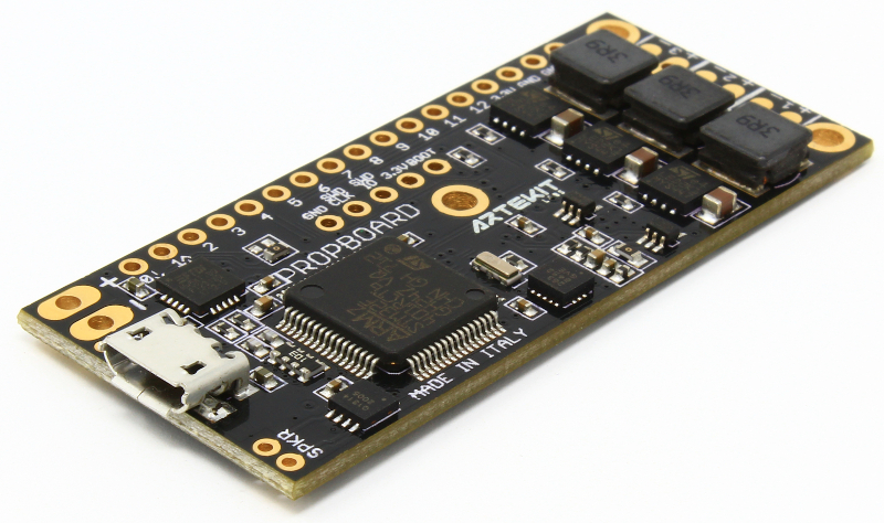
Top side
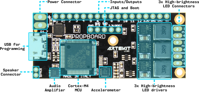
PropBoard top view
On the top side of the board there is:
Power Connector: Here you will connect your battery/power supply. The board comes in two power supply configurations: 5.5V to 12V range and 3.7V to 5V range. Follow this link to learn how to connect it and to change from one range to the other.
Inputs/Output: these are generic input/output pins. Click here to see a list of every pin function.
JTAG and Boot: used for connecting a JTAG plus an extra pin connected to the BOOT0 pin of the Cortex-M4 MCU.
3x High-brightness LED Connectors: this connector has a total of 6 pins to connect up to 3 high-brightness LEDs. Click here to learn how to connect your LEDs.
USB for Programming: a micro USB connector to connect the board to a PC/MAC. Used for downloading sketches from the Arduino IDE.
Speaker Connector: connect here your 4 Ohm or 8 Ohm speaker.
Audio Amplifier: a 2.9W Class-D mono audio amplifier. The ISSI IS31AP2005.
Cortex-M4 MCU: the microcontroller. A STmicroelectronics STM32F401RCT6 running at 84MHz, with 256kB of flash and 64kB of RAM.
Accelerometer: a digital 3-axis accelerometer. The NXP/Freescale MMA8452Q.
3x High-Brightness LED drivers: three STmicroelectronics LED2001A High-Brightness LED drivers and their coils.
Bottom side
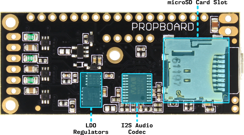
PropBoard bottom view
On the bottom side of the board there is:
microSD Card Slot with push-push technology. Used for storing audio files later to be played by the PropBoard.
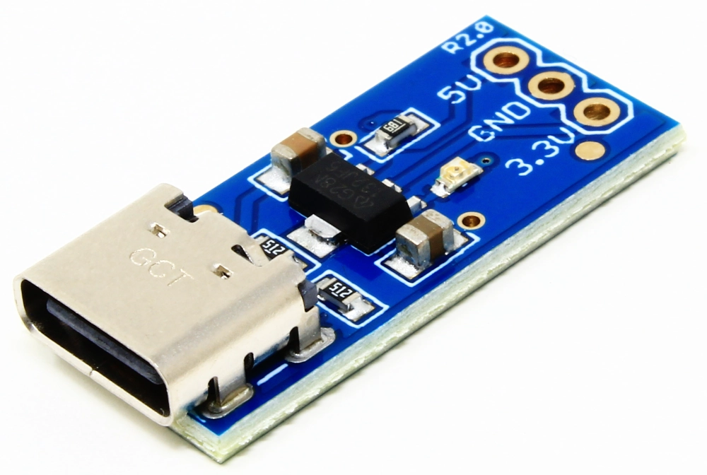
LDO regulators: in charge of converting the input power supply into 3.3V and 5V for powering the board components.
I2S Audio Codec: the Wolfson WM8523 digital-to-analog audio converter.
Connecting power/batteries
Locate the Power Connector. The connector has two pads to connect you power supply: one for the positive contact and one for the negative contact.
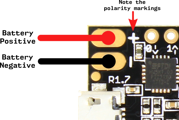
Power connector
The PropBoard supports two power supply ranges: 5.5V to 12V and 3.7V to 5V. You can change the power supply range anytime by following these instructions.
You can use two 18650 Li-ion batteries when the board is set to work in the 5.5V-12V range, or a single 18650 Li-ion battery when the board is set to work in the 3.7V-5V range.
A good rule of thumb: use quality, “thick” cables. Remember that in some conditions you will be drawing several amperes from the batteries. Cheap and thin cables will add resistance to the circuit, producing drops in the current supply when the board needs “power”. This will sometimes result in noticeable bad audio and LED dimming if the voltage drops below the minimum voltage input.
Note that the PropBoard does not have a polarity inversion protection circuitry. Connecting the power supply negative or positive contacts to the wrong pad can permanently damage the board.
Changing the power supply range
The PropBoard is optimized to work with a 5.5V to 12V power supply range, but you can change this range by making some modifications to the board. This is very useful if you want to use LED strips (see the LedStrip library).
The downside of the 3.7V to 5V range is that you will lose some audio output volume, and on some LEDs brands and/or colors (specially blue and green ones) there may be a brightness loss. In this case you may be able to compensate by incrementing the PWM duty cycle by setting a higher maximum forward current to the HBLED::begin function. To do this change in the code you have to be able to measure the LED power consumption with a multimeter on the LED output.
Remember that an excessive output current setting may damage your LEDs.
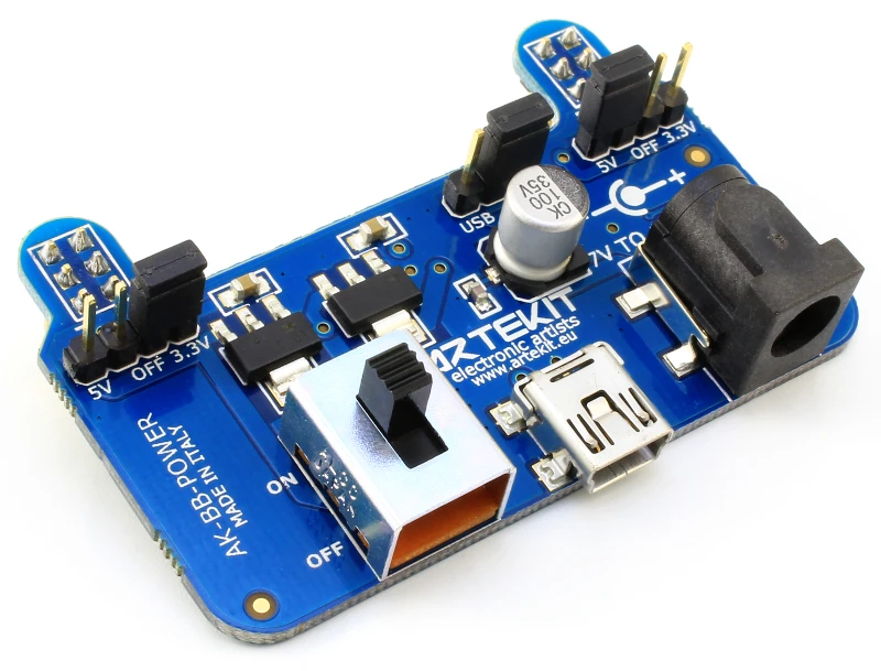
5.5V to 12V power supply range
Here follows a picture of a board set to operate in the 5.5V to 12V power supply range:
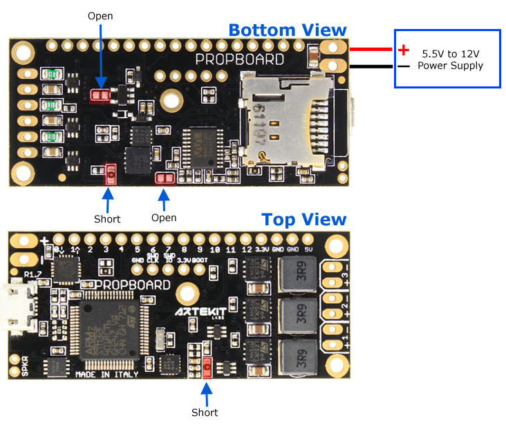
In the picture up here, the components pointed by “short” are 0 Ohm resistors (R13 and R19 in the schematics). If you have removed them already, short the pads with some solder. The other two pads (J7 and J10 in the schematics) are solder jumpers, that have to be open.
3.7V to 5V power supply range
If you want to use the 3.7V to 5V power supply range, make the following modifications:
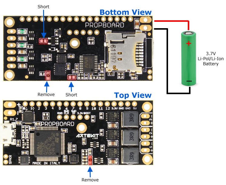
Short the pads marked as “short” (J7 and J10 in the schematics) with solder and remove the R0 resistors (R13 and R19 in the schematics).
When the board is configured to operate in 3.7V to 5V power supply range, applying a higher voltage than 5V can permanently damage the board. And of course, modifications to the board must be done with the batteries disconnected :)
Connecting the speaker
Locate the Speaker Connector. It is near to the SPKR label.
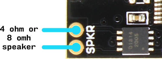
In these two pins you can connect a 4 ohm or a 8 ohm speaker. There is no polarity and you can connect the positive or negative signal of the speaker to any pad of this connector.
In order to output audio you need to provide power through the power connector. You will not be able to hear audio by just connecting the board with the USB cable.
Do not connect any of the speaker output terminals to Ground.
Connecting the LEDs
The PropBoard has 3 High-Brightness LED drivers. The recommended forward current of the LEDs is 700mA and up.
You can connect your LEDs on the connector with 6 pins.
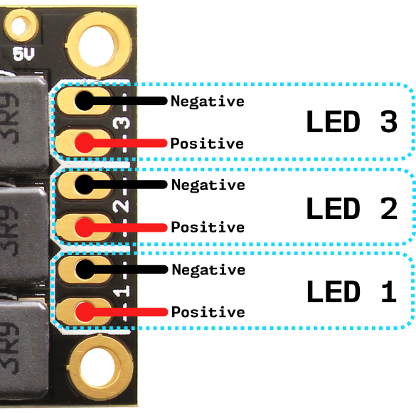
As shown in the picture above, there are 2 pins for each LED: one for the positive contact and one for the negative contact.
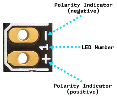
The connector markings are themselves very descriptive. For each LED there is a LED number, a positive pin and a negative pin, indicated with labels as in the picture here below.
You can access all these 3 outputs using the HBLED class described in the PropBoard LED API.
In order to use any of the LED outputs you need to provide power through the power connector. You cannot power the LEDs by just connecting the board with the USB cable.
Looking directly to High-brightness LED can permanently damage the eye. Use with caution.
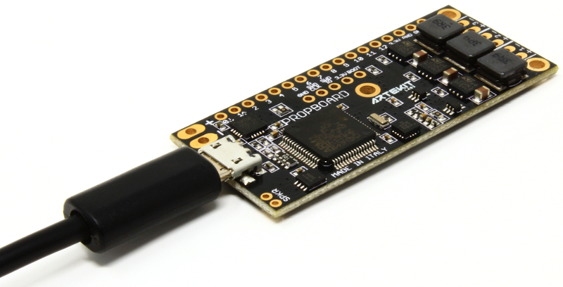
Connecting the USB cable
The PropBoard has a micro USB connector that can be used to power the board and to download sketches from the Arduino IDE.
The PropBoard uses a genuine FTDI chip to do the USB-to-Serial conversion. On Windows, OSX or Linux, the drivers will be automatically installed, if not already present in the operating system. In case you are asked for a driver, you can download it from here: http://www.ftdichip.com/Drivers/VCP.htm
The USB cable will also power the PropBoard if the batteries are not connected. You can safely use the USB and the battery on the power connector at the same time. If you are wondering if the USB will (intentionally or not) recharge the batteries, there is circuit dedicated to prevent it in order to protect your batteries from unwanted recharging.
Note that neither the LED outputs nor audio will work if the PropBoard is powered only through the USB connector.
Arduino IDE installation
The PropBoard can be programmed using the Arduino IDE. We have developed the software in a way it can be installed as a Board Package. From version 1.6.4 of the Arduino IDE you can easily download install 3rd party boards directly from the IDE. Also, each time you open the IDE, the Board Manager will check if there are new versions of the PropBoard software automatically.
Start by downloading and installing the standard Arduino IDE version that suits your operating system. Here is the link: https://www.arduino.cc/en/Main/Software
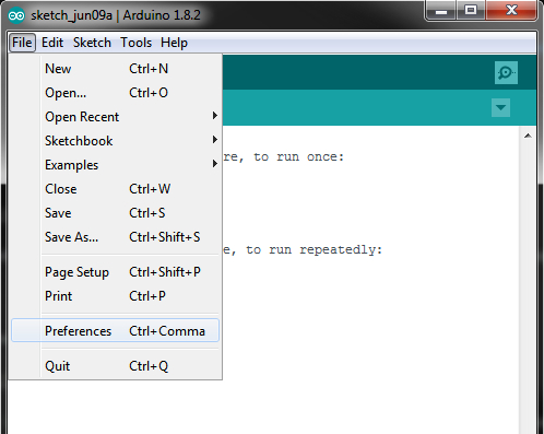
After installing the IDE, open it up and navigate to File -> Preferences.
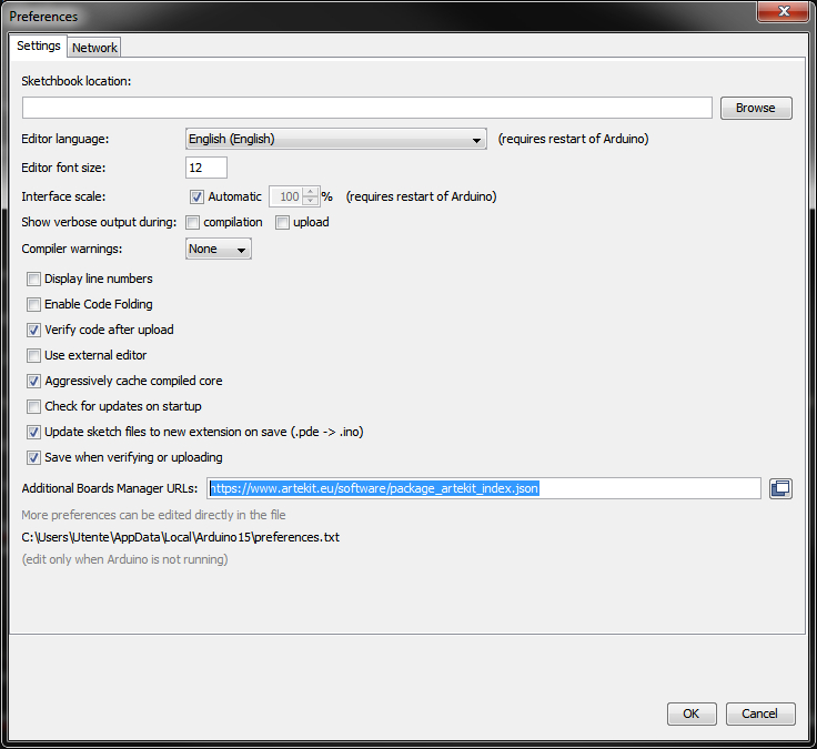
Then copy the following URL:
https://www.artekit.eu/software/package_artekit_index.json
Paste the URL into the Additional Board Manager URLs box, like in the picture here below. If you already have another URL in that box, you can add a comma at the end and paste the Artekit URL right after. Then click “OK”.
Now we proceed to actually install the PropBoard software. Copying and pasting the URL just says the Arduino IDE to download a list of boards that you can select later.
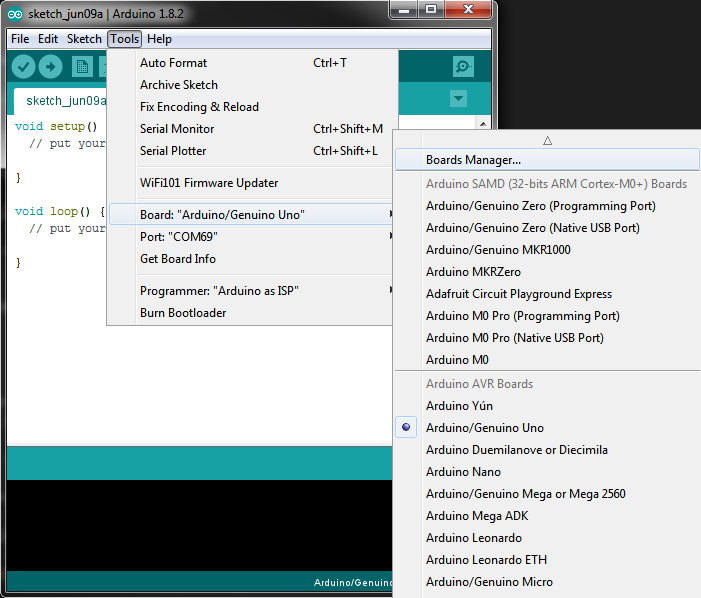
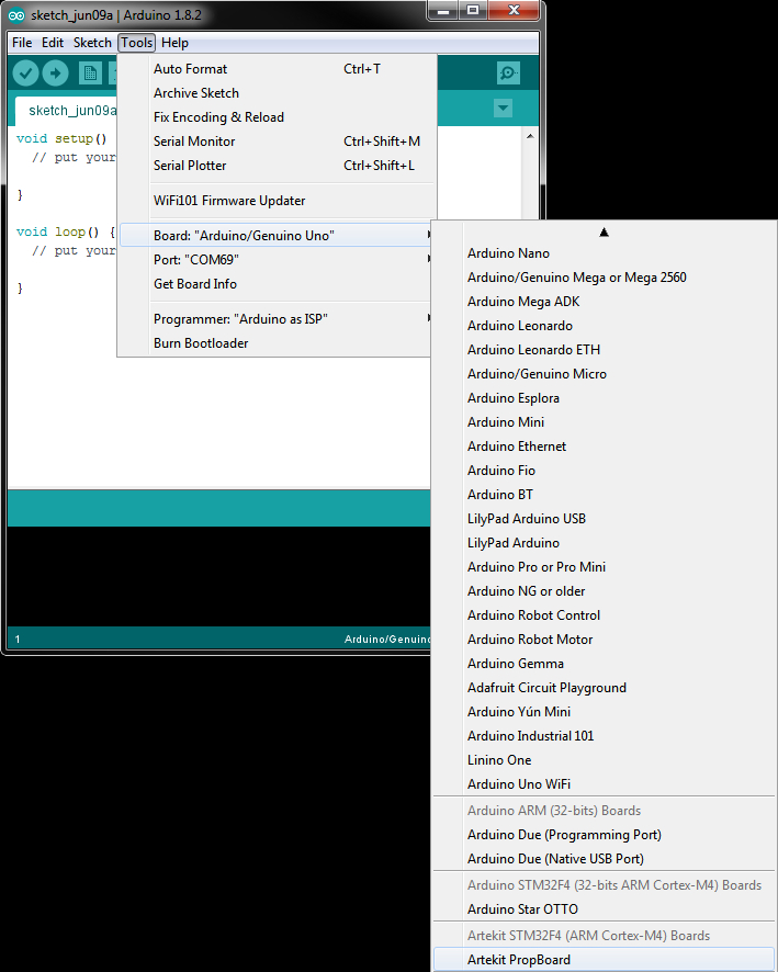
We do this by navigating to the Tools menu, go down to the boards section, and select Boards Manager from the menu, like in the picture here below.
A new window should open, showing a list of boards. Locate the Artekit PropBoard, select it and click on Install
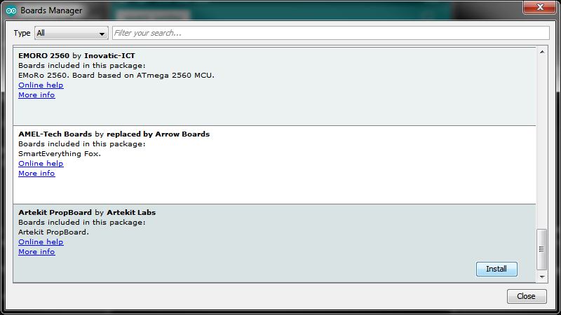
You should see now a progress bar indicating that the Board Package is being downloaded and installed. Wait for it to finish.
After that you should see a new board in the board list. Select the Artekit PropBoard.
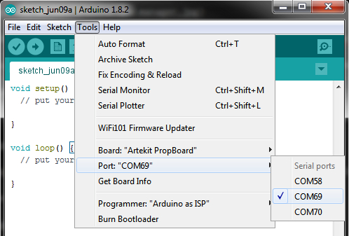
Connect the PropBoard to your PC/MAC with the USB cable as we have previously covered in this guide. You should then navigate to the Tools menu and then to the Port sub-menu. There select the serial port where the PropBoard is connected. For example, mine happens to be on COM69.
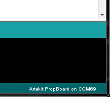
At the bottom of the window you should see Artekit PropBoard on COMXX.
That’s it! You are now ready to roll!
Learn about the API with the following guides:
Input/Output pins mapping
The PropBoard has 13 Input/Output pins for general purposes. Each pin has a number that can be used with the standard Arduino functions like digitalWrite, analogRead, etc. The other extra pins are described after the table here below.

Here follows a map of the input/output pins and their corresponding usage:
| PIN | PWM | IRQ | ADC | FUNCTION | PORT/PIN |
|---|---|---|---|---|---|
| 0 | NO | NO | NO | Serial1 RX | PC7 |
| 1 | YES | YES | NO | Serial1 TX | PA11 |
| 2 | NO | YES | NO | SCL (Wire) | PB10 |
| 3 | NO | YES | NO | SDA (Wire) | PB3 |
| 4 | YES | YES | YES | PB0 | |
| 5 | YES | YES | YES | PB1 | |
| 6 | YES | YES | YES | PA3 | |
| 7 | NO | YES | YES | PC4 | |
| 8 | NO | YES | YES | PC5 | |
| 9 | NO | NO | YES | CS (SPI) | PA7 |
| 10 | YES | NO | NO | MOSI (SPI) | PB5 |
| 11 | YES | NO | YES | MISO (SPI) | PA6 |
| 12 | YES | NO | YES | CLK (SPI) | PA5 |
Extra Pins
To the right of the Input/Output pins you can find four extra pins with the following functions:
The 3.3V pin outputs 3.3V from the internal LDO regulator. This regulator gives power the Cortex M4, microSD, accelerometer (and the audio amplifier in 3.7V-5V configuration). You can use it to supply power to external peripherals, or to connect the positive contact of, for example, a push button, but do not drain more than 80mA from it.
Then follows two GND pins, connected to the ground of the circuit. Connect it to the GND of external peripherals or use it as the negative contact of, for example, a push button.
The 5V pin outputs 5V from the internal LDO regulator. This regulator is used to supply power to the 3.3V internal LDO, and the audio amplifier in the 5.5V to 12V configuration. You can use it to supply power to external peripherals but do not drain more than 80mA from it.
Special internal pins
Here follows a map of some pins dedicated to internal functions of the board.
| PIN | PWM | IRQ | ADC | FUNCTION | PORT/PIN |
|---|---|---|---|---|---|
| 13 | NO | NO | NO | Audio Mute | PA15 |
| 14 | NO | YES | NO | Motion IRQ1 | PB7 |
| 15 | NO | YES | NO | Motion IRQ2 | PB6 |
| 16 | NO | NO | NO | 5V ON/OFF | PC1 |
| 17 | NO | NO | NO | 3.3V ON/OFF | PC2 |