Halloween Pumpkin Project
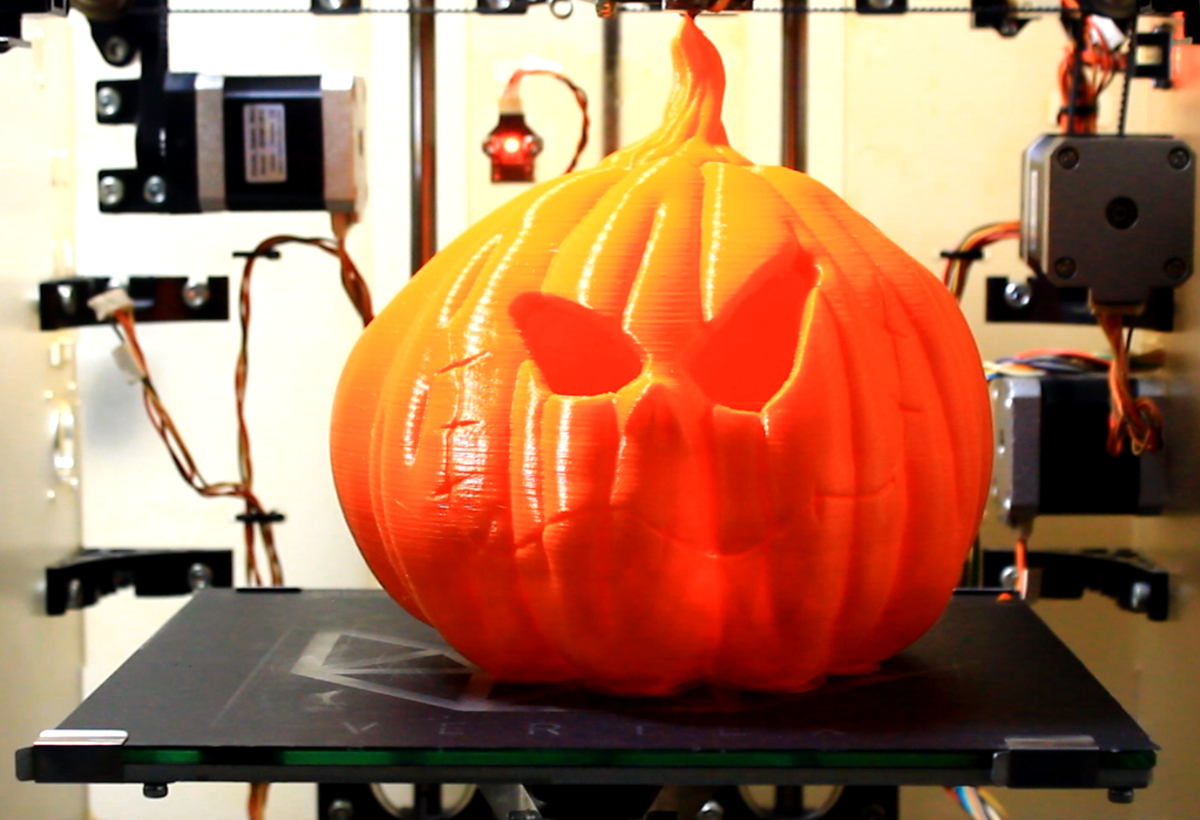
A 3D-printed Halloween pumpkin, with proximity detection and light/audio effects!
Introduction
In this tutorial we are going to use our Artekit PropBoard to give life to this fantastic 3D-Printed Halloween pumpkin.
We use some addressable RGB LEDs (a.k.a. Neopixels) to simulate the light from a candle. Using an infrared distance sensor we detect the presence of a person or object in front of the pumpkin. When the sensor is triggered we do a strobe effect with the LEDs while we play some scary audio file. A random music track or audio effect is played after some minutes of inactivity (no person presence detected).
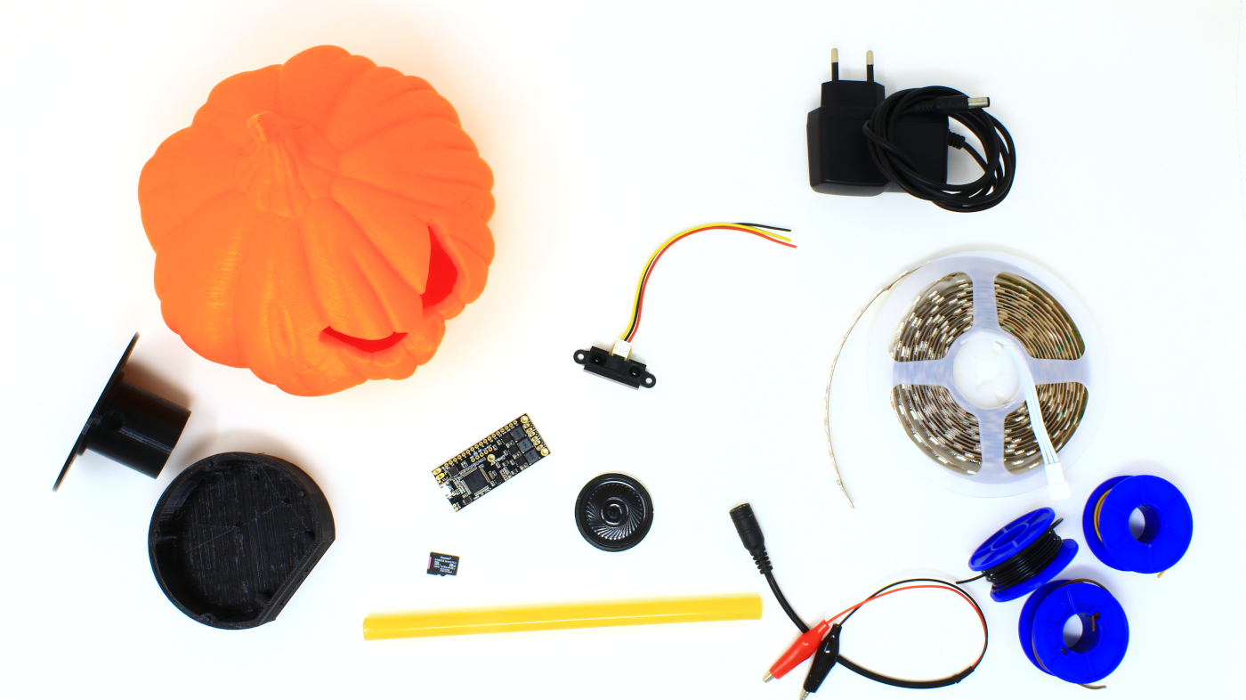
Required materials
- 3D-printed parts.
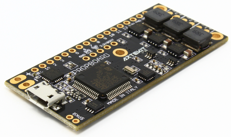
- An Artekit PropBoard.
- A GP2Y0A21YK0F IR distance sensor.
- Addressable LEDs strip (a.k.a. Neopixels): in our example we are using 20 WS2812B LEDs but APA102C and SK6812RGBW LEDs are supported too.
- MicroSD card for storing audio files.
- A 4Ω or 8Ω 40mm speaker.
- Some wires.
- Hot glue.
- A 5V power supply (500mA or above).
3D printing
All the model files for this project can be downloaded from Thingiverse by clicking the button here below:
Thingiverse: Halloween pumpkin 3D files
The files comprise:
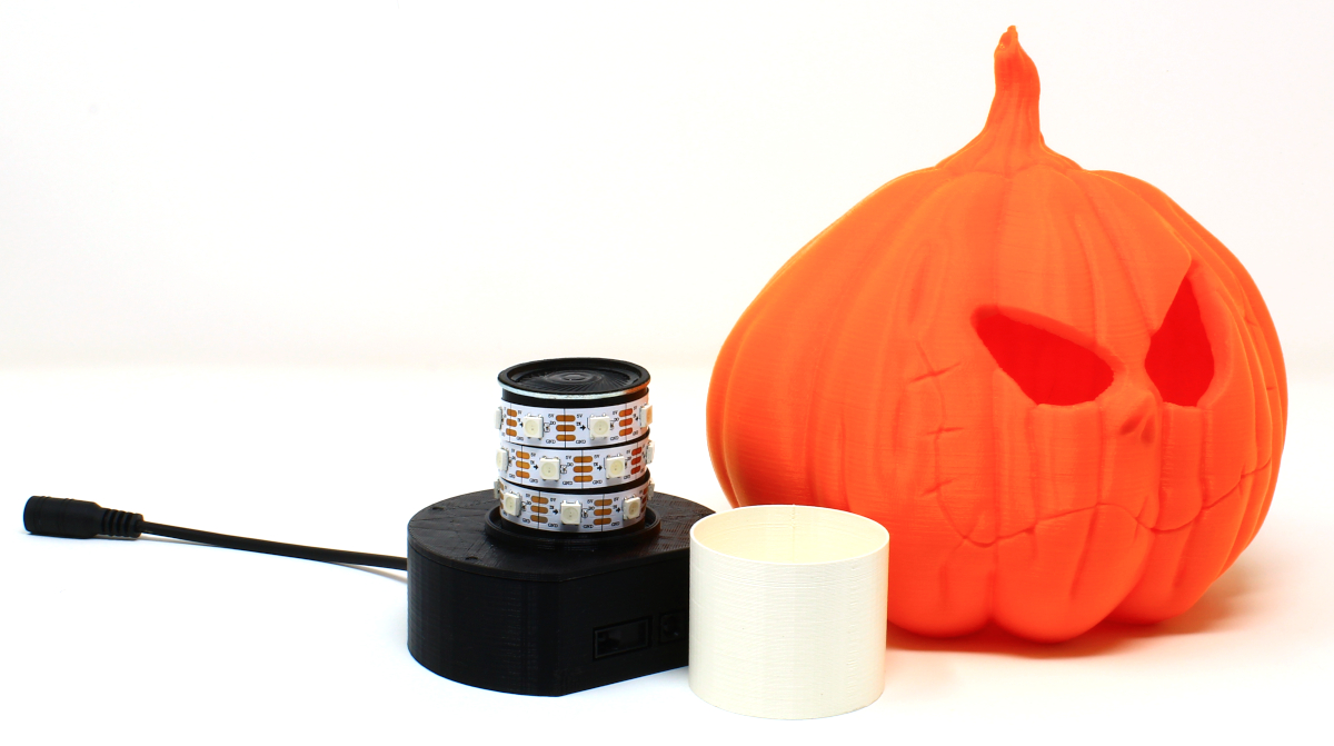
- The pumpkin (print this in orange PLA)
- A base with 4 little screws and the cover (print these with black PLA).
- An optional light diffusor you can put around the LEDs (to print in white PLA).
All the parts can be printed without supports. The longest part to print is of course the pumpkin (15 hours printing at 0.2mm).
Connections
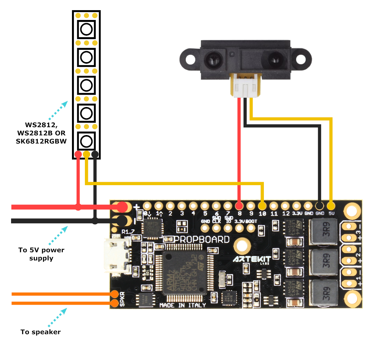
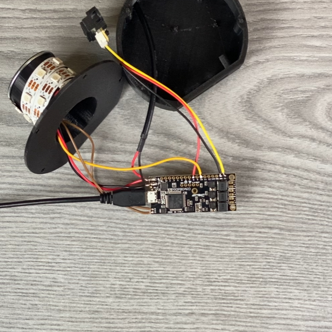
The following picture shows the required connections. The picture uses the same colors for the cables as shown in the video.
Note that the signal wire of the GP2Y0A21YK0F sensor is red, and the power supply wire is yellow.
Assembling
Before starting, make sure that your PropBoard is configured for the 5V-12V power supply range. If you have just purchased a new PropBoard you will be fine since the 5V-12V power supply range is the default one. If you have modified your PropBoard in the past, follow this procedure to bring back the 5V-12V range support.
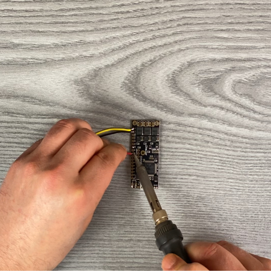 |
Start by soldering the sensor wires. Sensor VCC connected to PropBoard’s 5V, the data pin to pin 8 and ground to GND pin. |
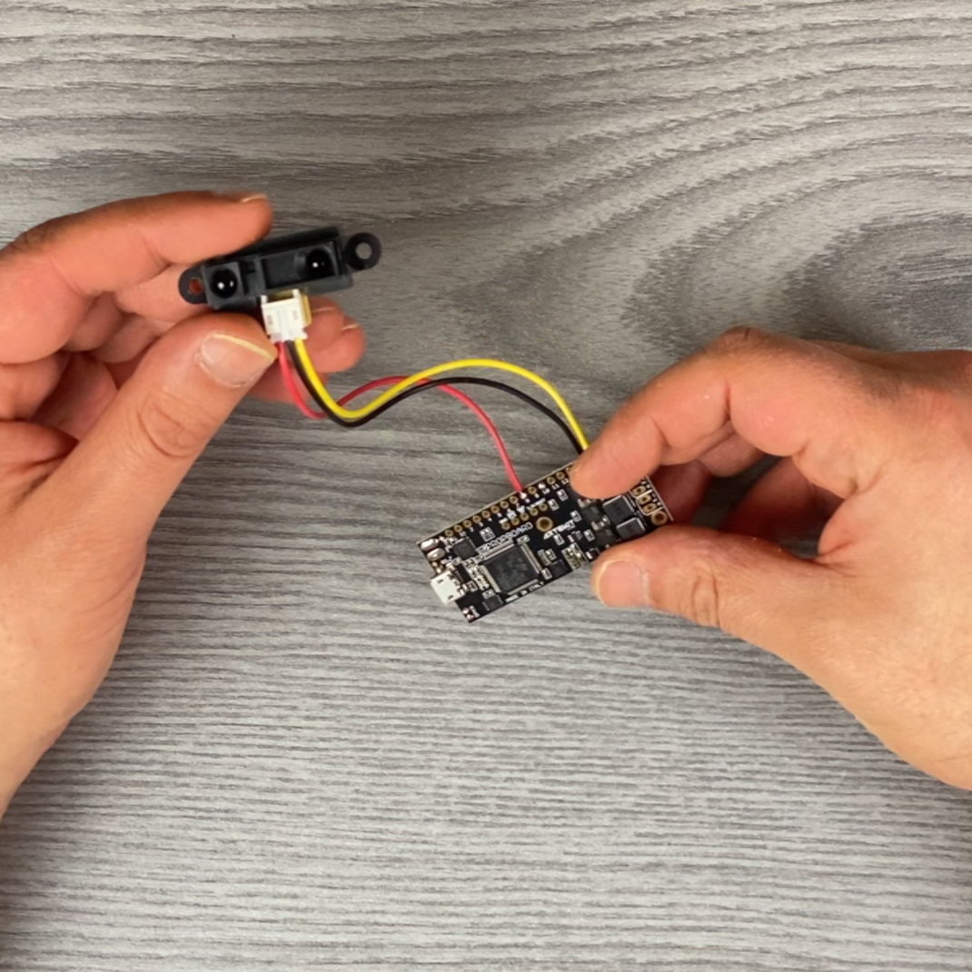 |
Wires shouldn’t be long since the sensor and the PropBoard will share a reduced space inside the black enclosure. You can measure this length by placing the PropBoard and the sensor inside the enclosure before soldering. |
 |
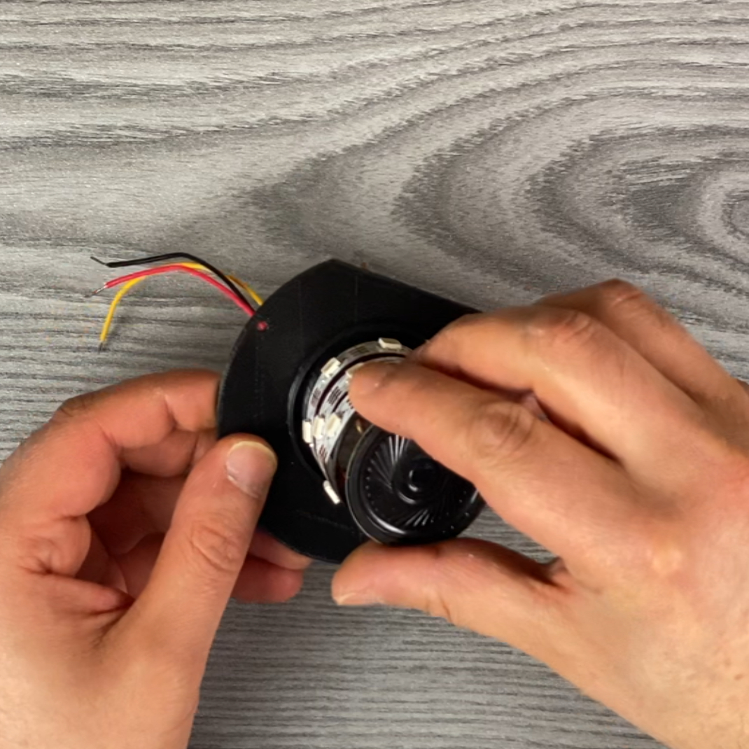
Calculate how many LEDs you will need. Take the cover and wrap some LEDs around it, starting by the little hole on the base. For this tutorial we are using 20 LEDs for a 60 LEDs per meter strip. Then cut the strip with scissors. |
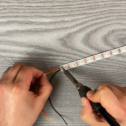 |
Solder the VCC, GND and data wires. ~10cm of wire should be enough. |
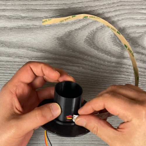 |
Put the LED strip wires through the hole. |
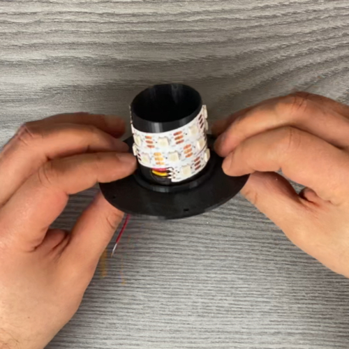 |
Then remove the adhesive protection and wrap the strip around the cover. |
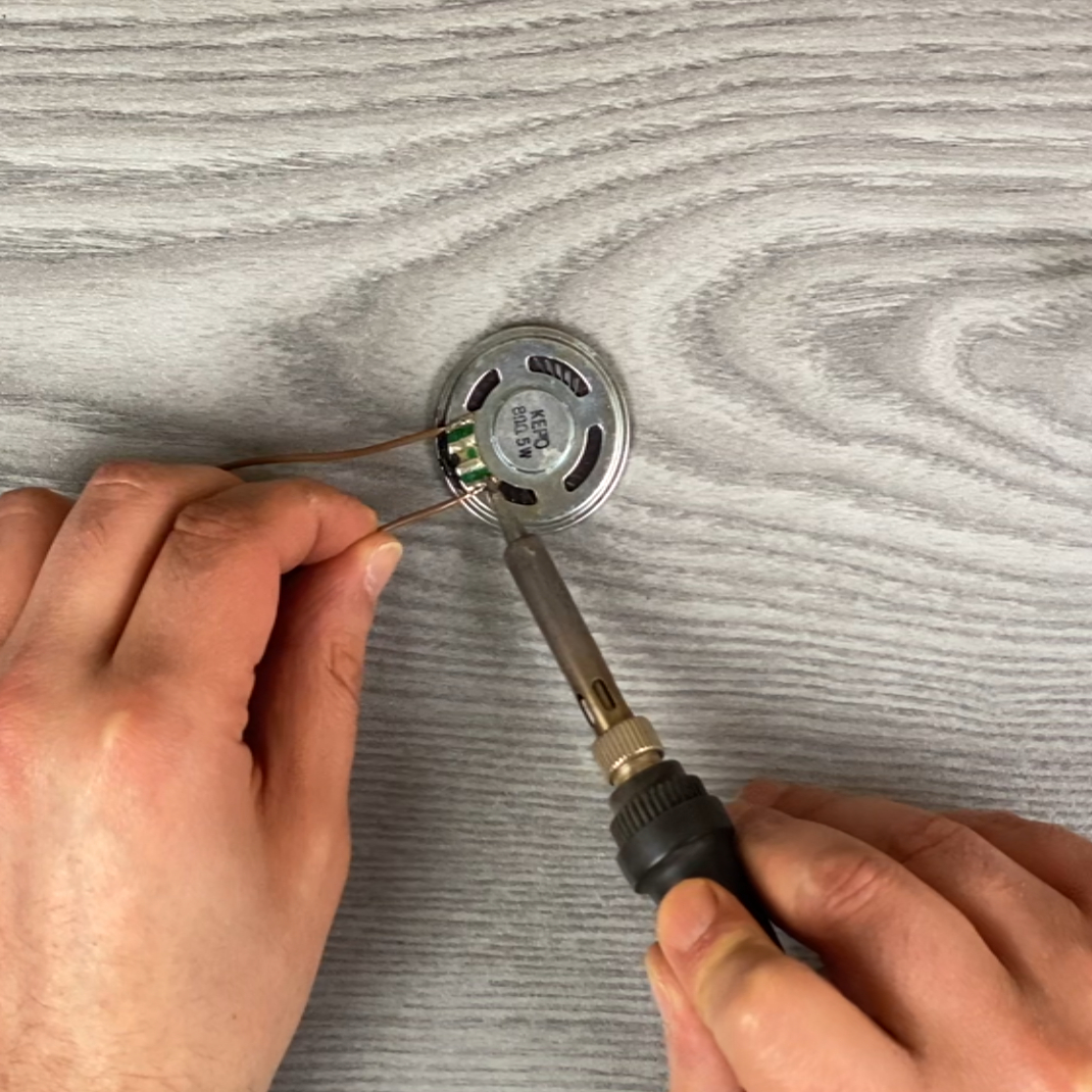 |
Solder two wires for the speaker. While measuring the length of the wires, consider that these wires will go from the top of the cover barrel down to the PropBoard. ~10cm should be fine. |
 |
Put the speaker wires through the cover and place the speaker on the top. |
 |
Then use the hot glue gun to put some glue on the back of the speaker, gluing it to the walls of the cover. |
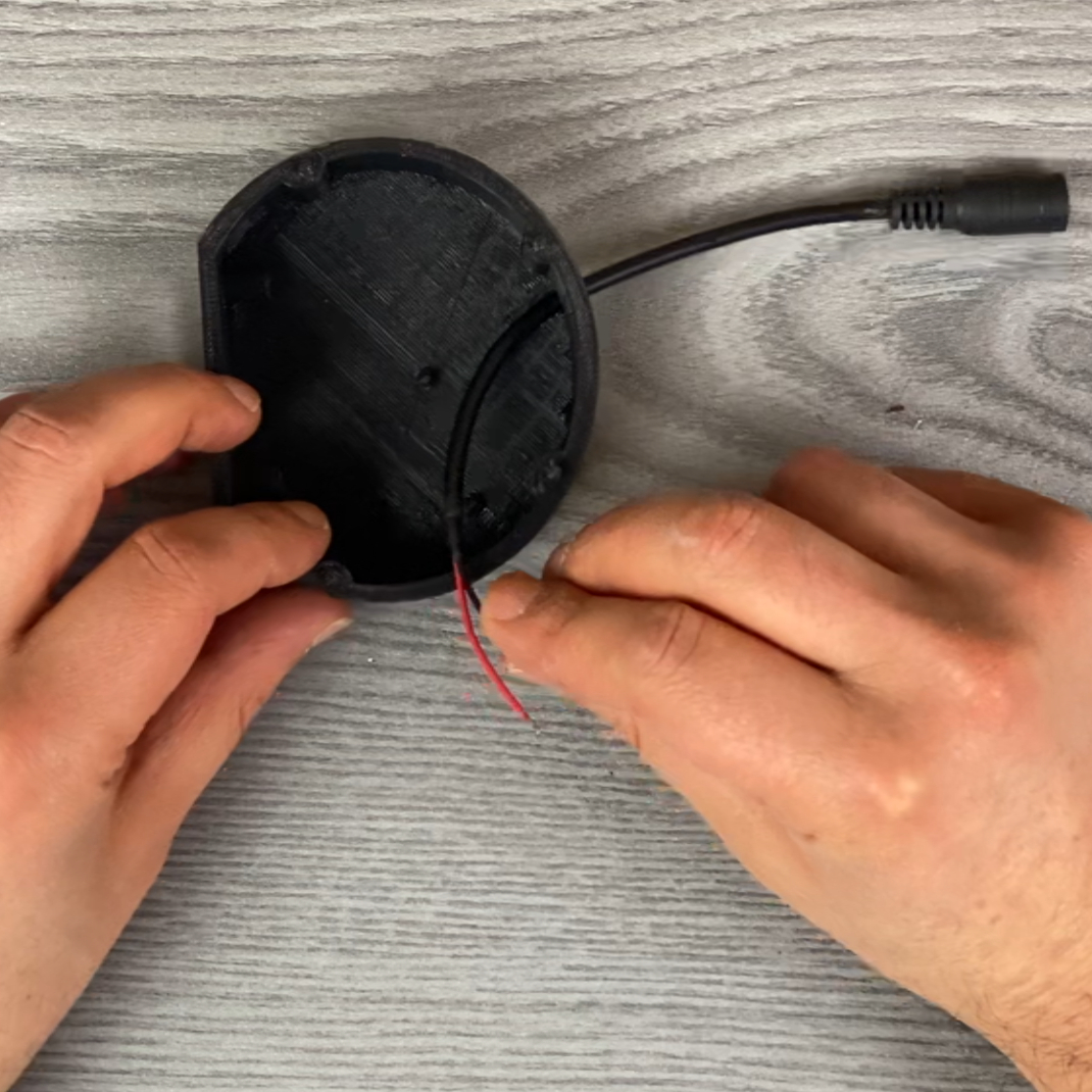 |
Put the power supply wires through the hole at the base. You can use any type of wire. We are using a DC Barrel Jack 2.1mm to Alligator Clips cable (we’ve cut the alligator clips). |
 |
Now bring the cover with the LEDs close to the base. Join the VCC and GND wires from the LEDs (red and black) with the wires of the power supply (red and black, respectively) and solder them together. |
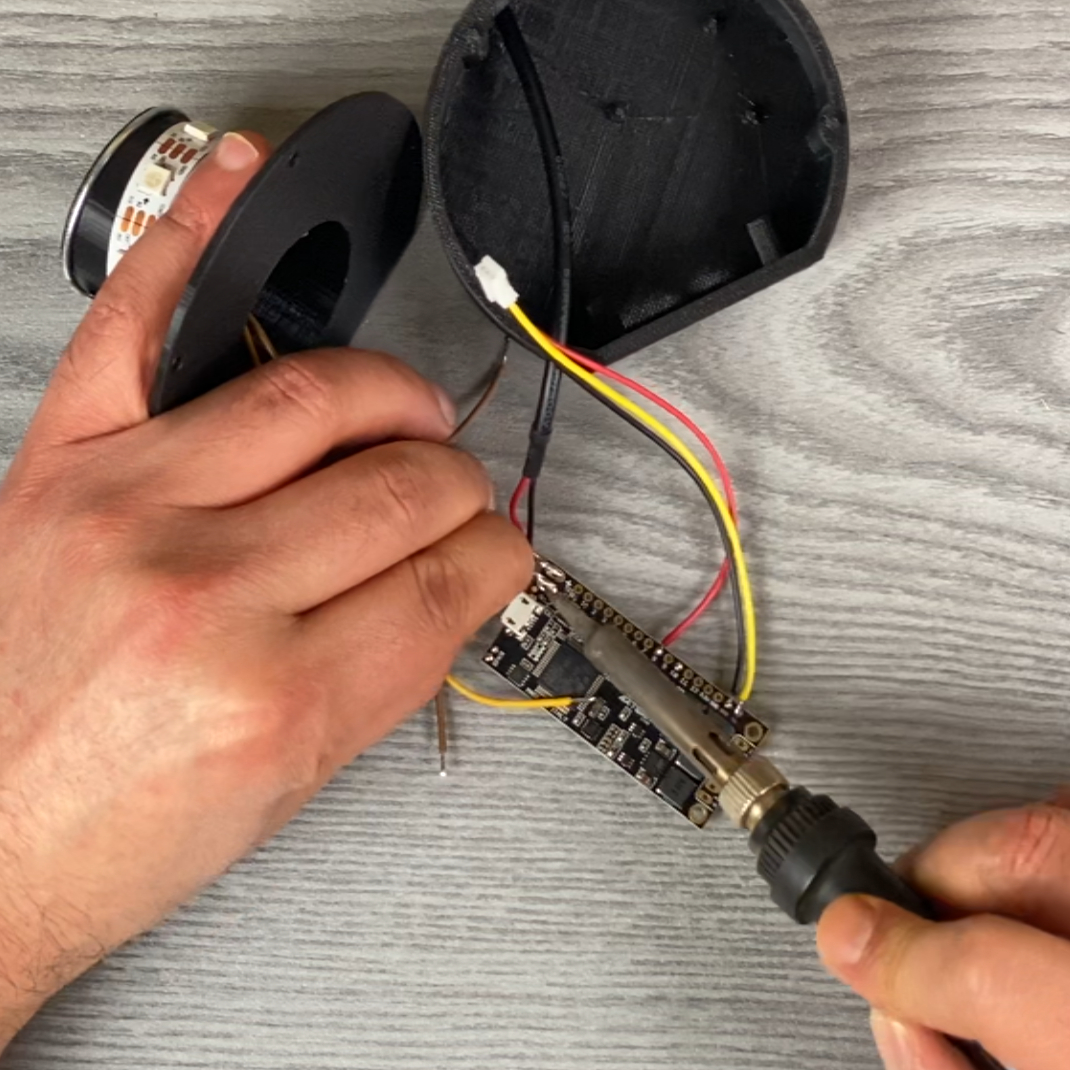 |
Solder the resulting power supply wires to the power supply pads on the PropBoard. The PropBoard power pads have the + and - markings, where you have to connect the red and black wires respectively. |
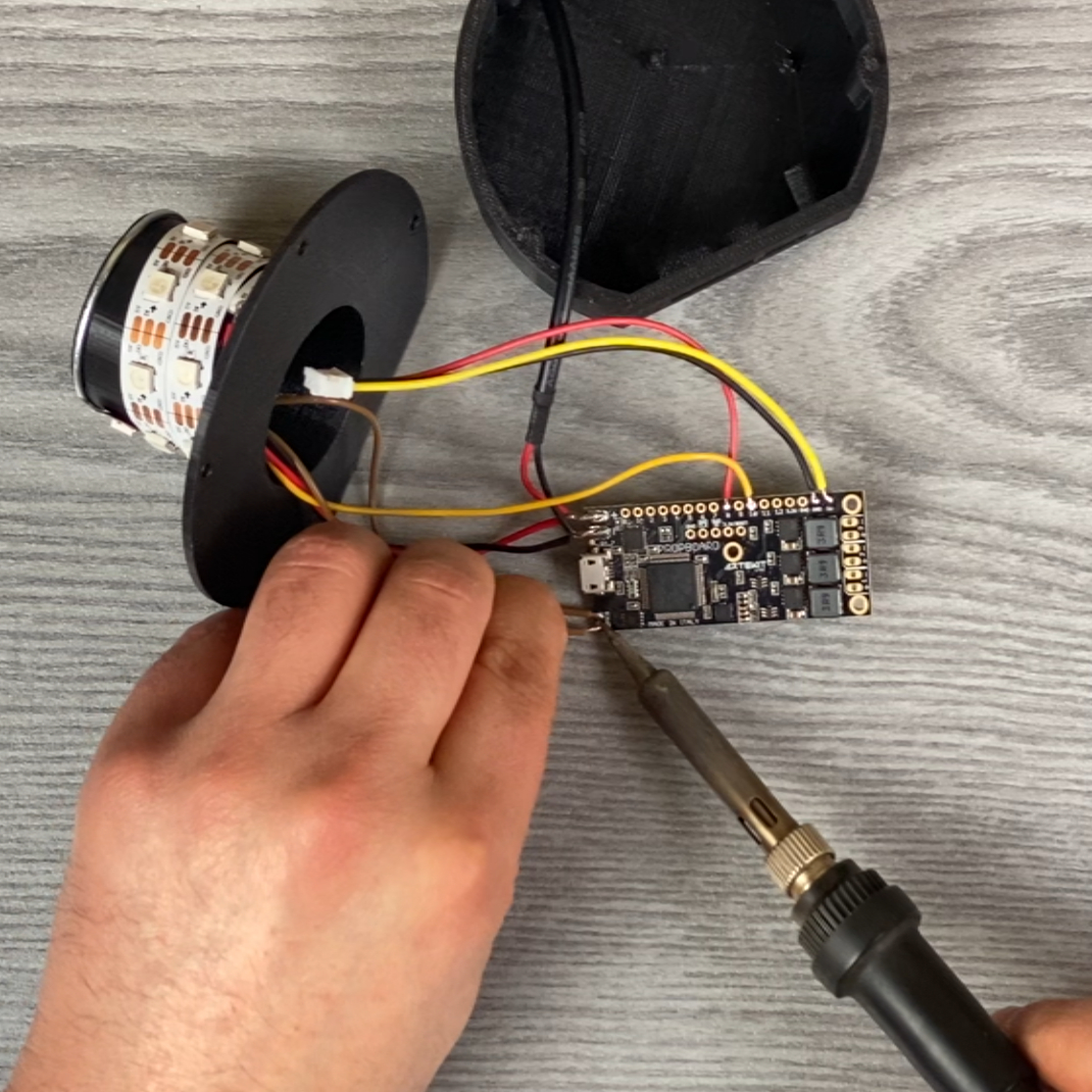 |
Solder the data wire coming from the LEDs strip to the pad 10 on the PropBoard Then solder the speaker wires on the speaker pads on the PropBoard. |
 |
Here we should connect the USB cable to the PropBoard and follow the steps in the Software section of this guide. We’ll imagine we’ve done that already and move onto the final steps. |
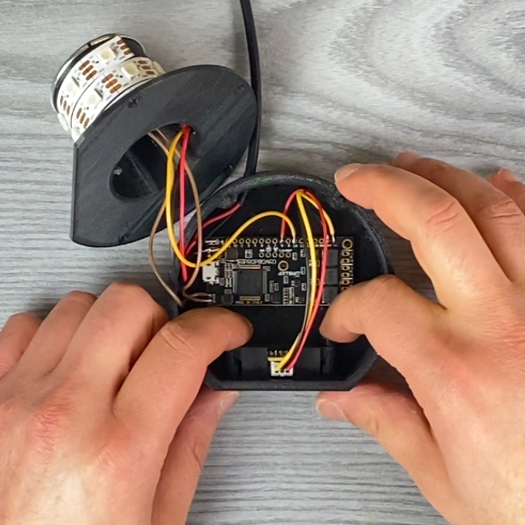 |
Disconnect the USB cable, insert the SD in the microSD slot and put the PropBoard inside the enclosure. There should be some little columns that fit the PropBoard mounting holes. Put the sensor in place (with connector facing up) and fix it using the little screws. |
Then put the cover and base together and the assembly is completed!
We suggest to paint the pumpkin’s mouth with black and the top with green acrylic paint, to enhance the contrast while the LEDs are doing the candle effect.

Software
Click in the button here below to download all the files, including the audio files we are using for this project.
There you will find the pumpkin folder with a sketch you have to open with the Arduino IDE. If this is your first time using the PropBoard, please install the PropBoard support for the Arduino IDE following these instructions.
After you have opened the sketch Arduino IDE, connect the PropBoard using a USB cable and click the Upload button.
The audio folder contains the audio files. Copy all these audio files to the root of the SD card.
Here follows the original code we are using for this project:
#include <LedStrip.h>

#define NUM_LEDS                            20
#define IDLE_TIME_AUDIO_SECONDS             180
#define TRANSITION_TIME_SECONDS             180
#define SENSOR_MIN_VALUE                    600
#define DISABLE_STROBE                      0
#define DISABLE_IDLE_AUDIO                  0
#define DISABLE_PRESENCE                    0
#define DISABLE_TRANSITION                  0

enum PumpkinState
{
    stateIdling,
    stateModeTransition,
    stateStrobe,
};

enum PumpkinIdleMode
{
    modeFire,
    modePulse,
};

static LedStrip led_strip;
static WavPlayer player;
static PumpkinState state;
static PumpkinIdleMode idle_mode;
static float brightness;
static bool transition_up;
static uint32_t idle_transition_ticks;
static uint32_t idle_audio_ticks;
static uint32_t transition_start_ticks;

void setup()
{
    pinMode(3, OUTPUT);
    pinMode(2, INPUT);

    #if DISABLE_PRESENCE == 0
    pinMode(8, INPUT);
    #endif

    Serial.begin(9600);
    Serial.println("Start");

    Audio.begin(44100);
    led_strip.begin(NUM_LEDS, WS2812B);
    led_strip.set(0, 0, 0, 0);
    led_strip.update();

    idle_mode = modeFire;
    enterState(stateIdling);
}

void loop()
{
    #if DISABLE_PRESENCE == 0
    uint32_t sensor_value = analogRead(8);
    #else
    uint32_t sensor_value = 0;
    #endif

    switch(state)
    {
        case stateModeTransition:
            if (millis() - transition_start_ticks >= 100)
            {
                transition_start_ticks = millis();

                if (transition_up)
                {
                    brightness += 0.05f;
                    if (brightness >= 1.0f)
                    {
                        brightness = 1.0f;
                        enterState(stateIdling);
                    }
                } else {
                    brightness -= 0.05f;
                    if (brightness <= 0.0f)
                    {
                        if (idle_mode == modeFire)
                            idle_mode = modePulse;
                        else
                            idle_mode = modeFire;

                        transition_up = true;
                        brightness = 0.0f;
                    }
                }

                led_strip.setBrightness(brightness);
            }

            pollLedStrip();
            break;

        case stateIdling:
            pollLedStrip();

            if (sensor_value >= SENSOR_MIN_VALUE)
            {
                enterState(stateStrobe);
            } else {
                #if DISABLE_IDLE_AUDIO == 0
                if (millis() - idle_audio_ticks >= IDLE_TIME_AUDIO_SECONDS * 1000)
                {
                    // Play some audio track
                    player.playRandom("idle", 1, 5);
                    idle_audio_ticks = millis();
                }
                #endif

                #if DISABLE_TRANSITION == 0
                if (millis() - idle_transition_ticks >= TRANSITION_TIME_SECONDS * 1000)
                {
                    // Transition into another LED pattern
                    enterState(stateModeTransition);
                    idle_transition_ticks = millis();
                }
                #endif
            }
            break;

        case stateStrobe:
            if (!player.playing())
            {
                led_strip.stopEffect();
                enterState(stateIdling);
            }
            break;
    }
}

void pollLedStrip()
{
    if (idle_mode == modeFire)
    {
        fire(20,120,40);
    } else {
        pulse();
    }
}

void pulse()
{
    static float pulse_brightness = 0.3f;
    static bool pulse_up = true;

    if (pulse_up)
    {
        pulse_brightness += 0.03f;
        if (pulse_brightness >= 1.0f)
        {
            pulse_brightness = 1.0f;
            pulse_up = false;
        }
    } else {
        pulse_brightness -= 0.03f;
        if (pulse_brightness <= 0.3f)
        {
            pulse_brightness = 0.3f;
            pulse_up = true;
        }
    }

    led_strip.setBrightness(pulse_brightness * brightness);
    led_strip.set(0, 255, 0, 0);
    led_strip.update();
    delay(10);
}

void enterState(PumpkinState new_state)
{
    switch(new_state)
    {
        case stateIdling:
            idle_audio_ticks = idle_transition_ticks = millis();
            brightness = 1.0f;
            break;

        case stateModeTransition:
            transition_start_ticks = millis();
            transition_up = false;
            break;

        case stateStrobe:
            #if DISABLE_STROBE == 0
            led_strip.stopEffect();
            led_strip.shimmer(RGB(255,255,255), 100, 10, false);
            #endif
            player.playRandom("motion", 1, 2);
            break;
    }

    state = new_state;
}

// Fire effect from:
// https://www.tweaking4all.com/hardware/arduino/adruino-led-strip-effects/#LEDStripEffectFire
void fire(int Cooling, int Sparking, int SpeedDelay) {
    static byte heat[NUM_LEDS];
    int cooldown;

    // Step 1.  Cool down every cell a little
    for( int i = 0; i < NUM_LEDS; i++) {
        cooldown = random(0, ((Cooling * 10) / NUM_LEDS) + 2);

        if(cooldown>heat[i]) {
            heat[i]=0;
        } else {
            heat[i]=heat[i]-cooldown;
        }
    }

    // Step 2.  Heat from each cell drifts 'up' and diffuses a little
    for( int k= NUM_LEDS - 1; k >= 2; k--) {
        heat[k] = (heat[k - 1] + heat[k - 2] + heat[k - 2]) / 3;
    }

    // Step 3.  Randomly ignite new 'sparks' near the bottom
    if( random(255) < Sparking ) {
        int y = random(7);
        heat[y] = heat[y] + random(160,255);
        //heat[y] = random(160,255);
    }

    // Step 4.  Convert heat to LED colors
    for( int j = 0; j < NUM_LEDS; j++) {
        setPixelHeatColor(j, heat[j] );
    }

    led_strip.update();
    delay(SpeedDelay);
}

void setPixelHeatColor (int Pixel, byte temperature) {
    Pixel++;

    // Scale 'heat' down from 0-255 to 0-191
    byte t192 = round((temperature/255.0)*191);

    // calculate ramp up from
    byte heatramp = t192 & 0x3F; // 0..63
    heatramp <<= 2; // scale up to 0..252

    // figure out which third of the spectrum we're in:
    if( t192 > 0x80) {                     // hottest
        led_strip.set(Pixel, 255, 255, heatramp);
    } else if( t192 > 0x40 ) {             // middle
        led_strip.set(Pixel, 255, heatramp, 0);
    } else {                               // coolest
        led_strip.set(Pixel, heatramp, 0, 0);
    }
}
Usage
Put the pumpkin on top of the assembly with the LEDs, connect the power supply and that’s it!
The program will play a short, random audio file every 5 minutes. If an object is detected in front of it, it will play some scary audio file while doing an strobe effect with the LEDs.
Customization
At the top of the Pumpkin sketch you can find the following definitions:
#define NUM_LEDS                    20
#define IDLE_TIME_AUDIO_SECONDS     300
#define TRANSITION_TIME_SECONDS     600
#define SENSOR_MIN_VALUE            600
#define DISABLE_STROBE              0
#define DISABLE_IDLE_AUDIO          0
#define DISABLE_PRESENCE            0
#define DISABLE_TRANSITION          0
You can modify these constants to configure the project behavior. Here follows an explanation:
NUM_LEDSis the number of LEDs in your strip. Ours has 20.IDLE_TIME_AUDIO_SECONDSis the interval in seconds in which the pumpkin plays a random audio track.TRANSITION_TIME_SECONDSis the time in seconds the pumpkin is idling (no presence detection) before it switches between fire and pulse LED patterns.SENSOR_MIN_VALUEyou can play with this value to configure the sensor readings (presence is detected farther if the values is smaller).DISABLE_STROBEwill disable the strobe effect after presence is detected (audio still plays).DISABLE_IDLE_AUDIOwill disable the random audio effect when the pumpkin is idling.DISABLE_PRESENCEdisables the presence detection.DISABLE_TRANSITIONdisables the LED pattern transition (the pumpkin will only do the fire effect).