Artekit AK-4XRS485/422 Line Drivers
This guide covers the Artekit AK-4XRS485/422, a RS485/422 driver, and the connection over a physical network.
Overview
The RS485 network, also known as TIA-485(-A) or EIA-485, is a widely used communication protocol. It finds its place in industrial environments due its high noise rejection and implements serial communications using balanced mode (differential pair) and multi-point systems. This mean that a network of devices can be connected together over long distances and in electrically noisy environments.
In this guide we are going to learn about the AK-4XRS485/422 board, a four-channel USB to RS485/422 line driver/converter in half-duplex configuration.
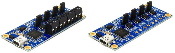
An AK-4XRS485/422 board with and without screw terminals.
Board characteristics
- RS485 channels
- 4 independent RS485/422 channels
- Each channels is driven by an ST485B RS485/422 transceiver IC
- Communication speed: 2.5Mbps (maximum)
- Common mode input voltage range: -7V to +12V
- Configuration: half-duplex
- Maximum 64 transceivers on each channel
For other channel specifications, please refer to the ST485 Line Driver datasheet.
Power
- USB Powered: from 4.5V to 5.5V
- Current consumption: 80mA (maximum)
Temperature
- Operating temperature: -40ºC to +85ºC
- Storage temperature: -60ºC to +150ºC
Functional description
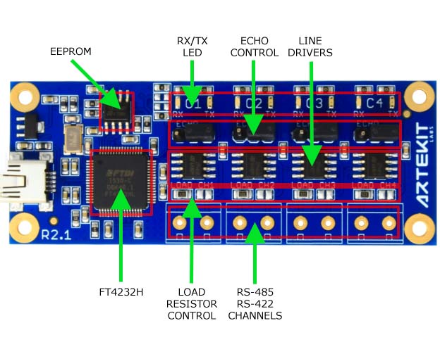
The board is based on the FTDI FT4232H IC that converts USB into RS485/422 protocol. It has four independent RS485/422 channels that are driven from the PC/MAC as virtual serial COM ports. The required FTDI drivers are supported on Windows, Linux and Mac OS.
On the board you can find the four RS485/422 channels, through screw terminal blocks or 3.5mm-spaced pins (the selection is done at the moment of purchase).
On every channel there is a jumper to enable/disable the transmitted character echo (required for some systems) and solder jumpers to enable/disable the on-board 120 Ohm load resistor.
The AK-4XRS485/422 board is powered directly through USB. No other power supply is required.
Channel settings
Each channel of the AK-4XRS485/422 board has a jumper to enable/disable the character echo, and a solder jumper to enable/disable the 120 Ohm load resistor. By default the echo disabled and the load resistors are disabled.
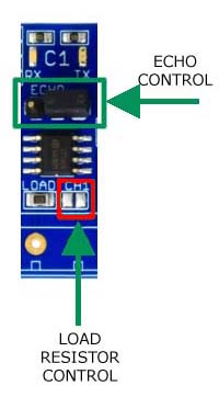
To enable the echo, move the jumper to the ECHO position. To enable the load resistor, join the pads with some solder.
Connecting the board
Install the FTDI drivers if these are not already installed. Connect the USB cable and wait some seconds for Windows to enumerate the USB devices.
Open the Device Manager.
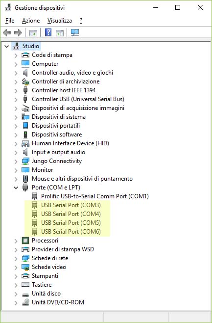
Now the Device Manager shows four new COM ports (note that the channel numbers could change according to you computer settings and if you previously have installed other FTDI chips).
The lower COM number is the RS485/422 channel 1, and the highest COM number is the RS485/422 channel 4. All data sent/received to/from this COM ports is sent/received to/from the respective RS485/422 board channel.
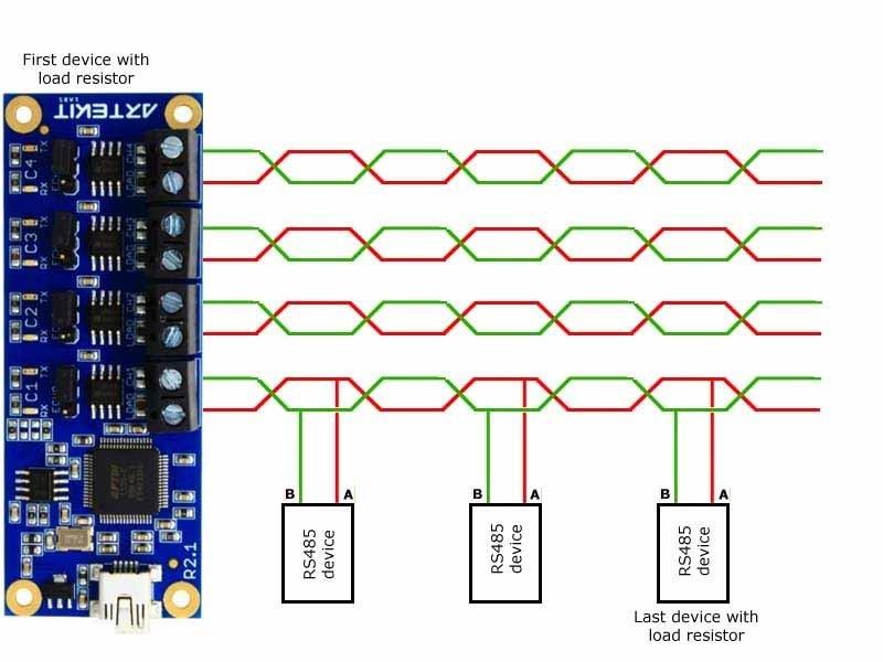
Connecting the board to a RS485 network
Here follows a typical example on how to connect the board to a RS485/422 network.