Artekit AK-MCP2221 Breakout
Everything you need to know about the Artekit AK-MCP2221 Breakout board.
Introduction
The Artekit AK-MCP2221 Breakout board is a do-it-all, USB bridge-to-I2C/UART/GPIO.
The AK-MCP2221 breakout board is a based on the Microchip MCP2221 USB Bridge and allows you to do USB-to-Serial and USB-to-I2C conversion plus using general purpose pins as inputs, output, ADC, DAC and more.
The board can operate at 3.3V or 5V logic level by using the on board switch.
Suggested reading: I²C Communication Protocol
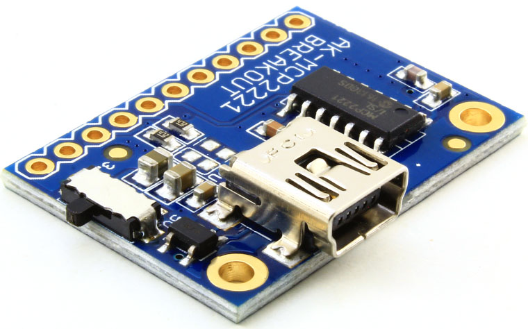
Hardware overview
Let’s take a look at the board. On the top side there is the USB connector, where you will connect the board to a PC/MAC using a cable with a mini USB connector. There is also the 3.3V/5V Switch that allows you to change the operating voltage of the board. It is recommended to operate the switch with the board disconnected from the host.
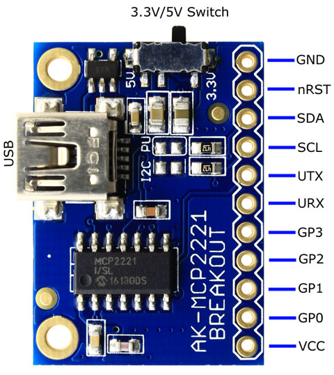
On the right there is a row of 11 pins with 1” (2.54mm) pin pitch. Details about the pins are in the table here below.
| Pin | Type | Description |
|---|---|---|
| GND | POWER | Board ground |
| nRST | IN | Active Low. Resets the board |
| SDA | IN/OUT | I2C data input/output (SDA) |
| SCL | OUT | I2C clock output (SCL) |
| UTX | OUT | UART data output (TX) |
| URX | IN | UART data input (RX) |
| GP3 | IN/OUT | General Purpose I/O or special function pin: LED_I2C (OUT): USB-I2C traffic indicator LED (factory default) ADC3 (IN): ADC Channel 3 DAC2 (OUT): DAC Output 2 |
| GP2 | IN/OUT | General Purpose I/O or special function pin: USBCFG (OUT): USB device Configured status (factory default) ADC2 (IN): ADC Channel 2 DAC1 (OUT): DAC Output 1 |
| GP1 | IN/OUT | General Purpose I/O or special function pin: CLKR (OUT): Clock Reference Output ADC1 (IN): ADC Channel 1 LED_UTx (OUT): UART TX Activity LED (factory default) IOC (IN): External interrupt edge detector |
| GP0 | IN/OUT | General Purpose I/O or special function pin: SSPND (OUT): Host enter in suspend mode LED URx (OUT): UART RX Activity LED (factory default) |
| VCC | POWER | VCC output (500mA in 5V mode, <300mA in 3.3V mode) |
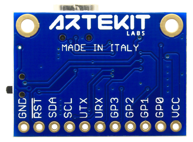
All the pins here above are also indicated in the bottom of the board, with labels.
Use the 3.3V/5V switch, all output signals will be adjusted to the selected voltage, including the VCC pin.
The AK-MCP2221 board can drive an output current up to 500mA in 5V mode, limited only by the USB Host, and <300mA in 3.3V mode.
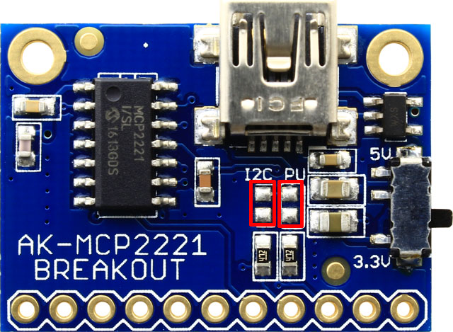
I2C pull-up resistor
The AK-MCP2221 breakout board includes two 4.7K resistors to be used as I2C pull-ups. Drop solder over the two pads indicated with red in the picture here below to activate the pull-ups. Use these pull-ups only if there are no other pull-ups resistors already present in the I2C bus.
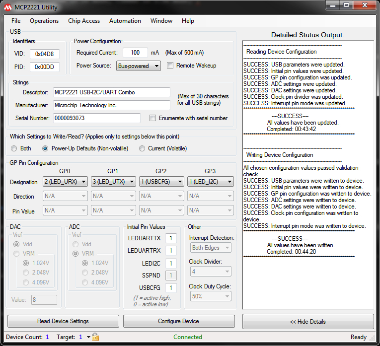
Software
The MCP2221 IC comes with drivers for Linux, Windows and OSX, plus libraries for JAVA, .NET and several utility programs. You can find all this at the Microchip page or in the list at the bottom of this page.
We suggest you to start by using the MCP2221 Utility to get familiarized with the board/chip. There you will be able to explore the many possible configurations the MCP2221 has to offer.
Connection example using sensors
The AK-MCP2221 board is a great choice when it comes to connect sensors to be managed from the PC. The picture here below shows the typical connections needed to drive two sensors. In this example the sensors are the Artekit AK-MMA8452Q 3-Axis Accelerometer and the Artekit AK-MAG3110 3-Axis Digital Magnetometer.
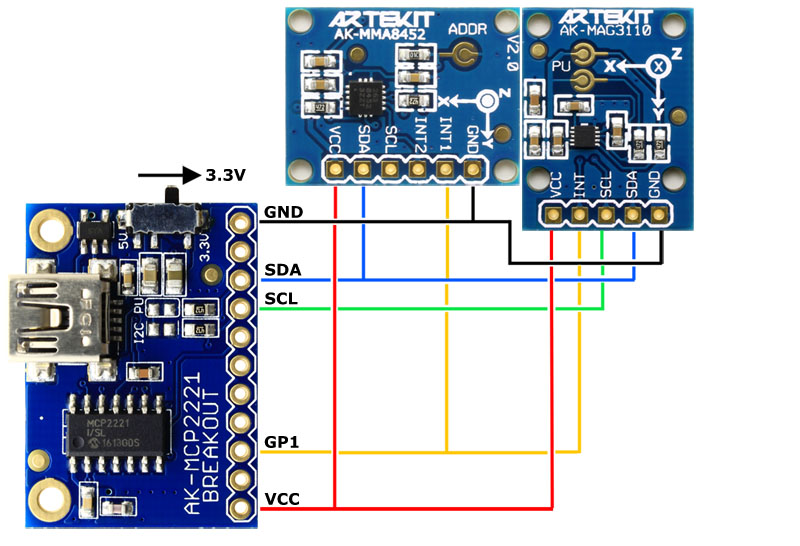
The sensors get the power from the AK-MCP2221 board. Remember to set the switch to operate at 3.3V before connecting the USB cable.
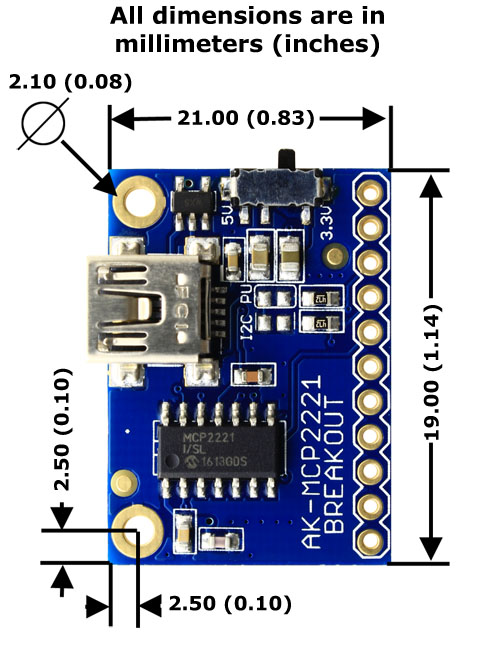
Board dimensions
Additional resources
- MCP2221 datasheet
- MCP2221 utility program
- MCP2221 MCP2221 Linux Kernel I2C Bus Driver
- MCP2221 Terminal Android App (v2.0)
- MCP2221 Java Native Interface (v1.0)
- MCP2221 I2C/SMBus Terminal (v2.0)
- MCP2221 DLL (v2.1.1)
- MCP2221 Windows Driver & Installer
- MCP2221 Mac Driver Information
- MCP2221 Linux Driver Information
- Artekit AK-MCP2221 schematics
- Artekit AK-MCP2221 product page