Artekit AK-APDS-9250 RGB+IR sensor
User manual for the AK-APDS-9250 Light Sensor breakout.
Introduction
The AK-APDS-9250 is a breakout board for the Avago Technologies APDS-9250, a light sensor that can be used to measure light intensity delivering values for each red, green, blue and infrared channels.
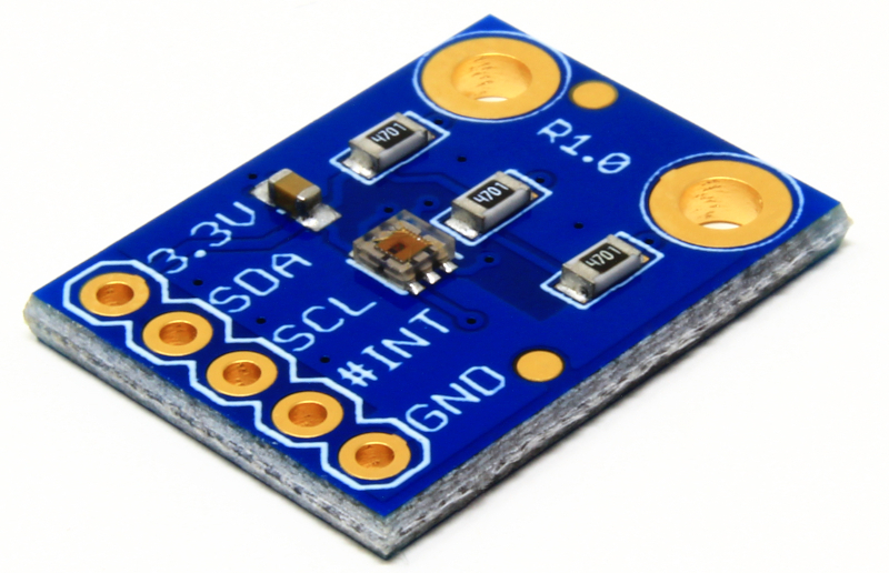
Artekit Labs AK-APDS-9250 board.
By using the I2C (or Arduino Wire) you can get values for light intensity independently by RGB+IR channels, or you can use it as a generic ambient light sensor.
APDS-9250 characteristics
- Light sensor with RGB and IR channels.
- 3.3V typical power supply.
- I2C communication.
- 20-bit resolution.
- Optional interrupt pin.
- Low power consumption.
Applications
- Ambient light color sensing.
- Backlight control.
Hardware overview
The AK-APDS-9250 breakout board exposes the required connections to operate the APDS-9250 chip by breaking-out its pins into 0.1” (2.54mm) spaced pins.
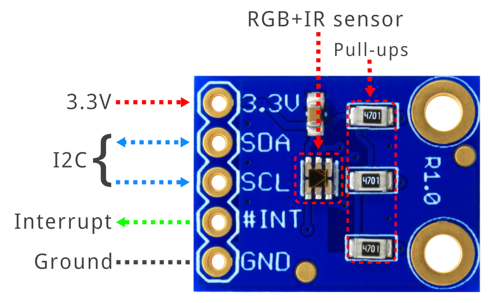
Hardware overview, top side.
In sum, the available connections are:
| PIN | Type | USAGE |
|---|---|---|
| 3.3V | PWR | POWER: 3.3V Power Supply |
| SDA | IN/OUT | I2C SDA signal (Open Drain) |
| SCL | IN | I2C SCL signal (Open Drain) |
| #INT | OUT | Interrupt signal (Open Drain) |
| GND | PWR | Ground |
On the bottom side of the board you can find three solder jumpers to enable the 4.7K Ohm pull-up resistors (disabled by default). These pull-ups are connected in parallel with the I2C lines and the interrupt pin. If your host board does not have the pull-up resistors on board, or there are not pull-up resistors anywhere in your I2C bus, then you must enable them by dropping some solder and joining the jumpers.
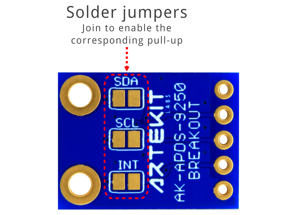
Hardware overview, bottom side.
Connections to an Arduino UNO
The Arduino Uno operates only with 5V devices, so to use the AK-APDS-9250 with an Arduino we will need a level translator. In this example we will use the Artekit AK-TXS0108.
Suggested reading: Using Logic Level Converters
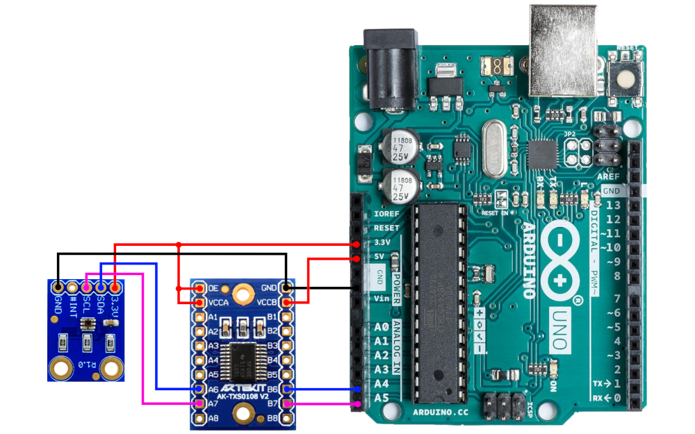
How to connect the AK-APDS-9250 to an Arduino UNO
Generic 3.3V MCU connections
If you use a 1.7V to 3.3V MCU the connection will be much more simpler, and you can save the Voltage Level Converter by connecting the AK-APDS-9250 Breakout Board directly to your MCU:
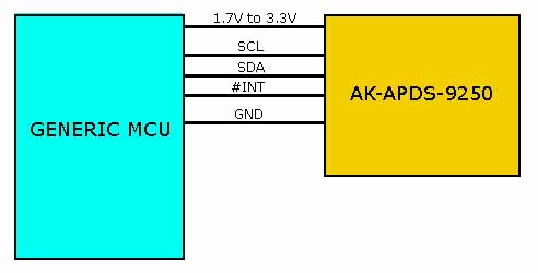
Connections to a generic 1.7V-3.3V MCU
Library for Arduino
We have prepared a library for Arduino that you can download by clicking on the button here below.
Artekit AK-APDS-9250 Arduino Library
To install it, go to the Sketch menu and select Include Library and then Add .ZIP library. Select the file you have downloaded.
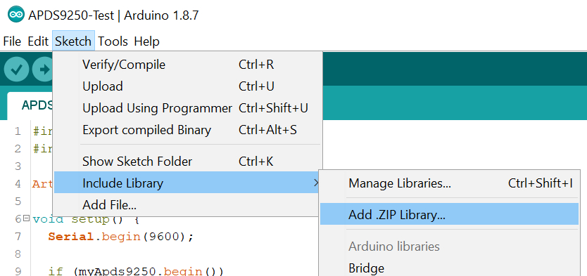
Library installation
Example 1: Simply reading
You can find the following code in the Examples menu. It will test all the modes and then start outputting the RGB values every second. You can see the values using the Serial monitor at 9600bps.
#include <Wire.h>
#include "Artekit_APDS9250.h"

Artekit_APDS9250 myApds9250;

void setup() {
  Serial.begin(9600);

  if (myApds9250.begin())
  {
    Serial.println("begin() OK");
  }

  Serial.print("setMode():");
  Serial.println((int) modeColorSensor);
  myApds9250.setMode(modeColorSensor);
  Serial.print("Mode: ");
  Serial.println((int) myApds9250.getMode());

  Serial.print("setMode():");
  Serial.println((int) modeAmbientLightSensor);
  myApds9250.setMode(modeAmbientLightSensor);
  Serial.print("Mode: ");
  Serial.println((int) myApds9250.getMode());

  for (int i = 0; i <= res13bit; i++)
  {
    Serial.print("setResolution():");
    Serial.println(i);
    myApds9250.setResolution(i);
    Serial.print("Resolution: ");
    Serial.println((int) myApds9250.getResolution());
  }

  for (int i = 0; i <= rate2000ms; i++)
  {
    Serial.print("setRate():");
    Serial.println(i);
    myApds9250.setMeasurementRate(i);
    Serial.print("Rate: ");
    Serial.println((int) myApds9250.getMeasurementRate());
  }

  for (int i = 0; i <= gain18; i++)
  {
    Serial.print("setGain():");
    Serial.println(i);
    myApds9250.setGain(i);
    Serial.print("Gain: ");
    Serial.println((int) myApds9250.getGain());
  }

  myApds9250.setMode(modeColorSensor);
  myApds9250.setResolution(res18bit);
  myApds9250.setGain(gain1);
  myApds9250.setMeasurementRate(rate100ms);
}

void loop()
{
  uint32_t r, g, b, ir;
  myApds9250.getAll(&r, &g, &b, &ir);
  char str[64];
  sprintf(str, "r:%lu g:%lu b:%lu ir:%lu", r, g, b, ir);
  Serial.println(str);

  delay(1000);
}
Example 2: color detection
The following code can be also found in the Examples menu. Using the AK-APDS-9250, the Arduino UNO will detect the color of the LED in front of the color sensor and will use its output to turn on an LED of the same color (except for infrared; a yellow LED is used).
For this example we have used:
- An Arduino UNO
- One AK-APDS-9250 color sensor
- One AK-TXS0108 level converter
- Two mini breadboards
- A 400-point solderable breadboard
- Jumper wires
- Two 5mm LEDs the following colors:
- A 5mm yellow LED
- A 5mm infrared LED (850nm)
- A 9V battery snap for powering the LEDs on the solderable breadboard
- A 9V battery snap with plug for powering the Arduino
The code for the example is the following:
#include <Wire.h>
#include <Artekit_APDS9250.h>

#define PIN_RED     5
#define PIN_GREEN   4
#define PIN_BLUE    3
#define PIN_IR      2

Artekit_APDS9250 myApds9250;

void setup() {

  pinMode(PIN_RED,OUTPUT);
  pinMode(PIN_GREEN,OUTPUT);
  pinMode(PIN_BLUE,OUTPUT);
  pinMode(PIN_IR,OUTPUT);

  digitalWrite(PIN_RED,HIGH);
  digitalWrite(PIN_GREEN,HIGH);
  digitalWrite(PIN_BLUE,HIGH);
  digitalWrite(PIN_IR,HIGH);

  Serial.begin(9600);
  Serial.println("Serial OK");
  if (myApds9250.begin())
  {
    Serial.println("begin() OK");
  } else {
    Serial.println("begin() FAIL");
  }

  myApds9250.setMode(modeColorSensor);
  myApds9250.setResolution(res18bit);
  myApds9250.setGain(gain9);
  myApds9250.setMeasurementRate(rate100ms);
}

void loop()
{
  uint32_t r, g, b, ir;
  myApds9250.getAll(&r, &g, &b, &ir);
  char str[64];
  sprintf(str, "%lu %lu %lu %lu", b, r, g, ir);
  Serial.println(str);

  if (r > 3000) {
    digitalWrite(PIN_RED,LOW);
  } else {
    digitalWrite(PIN_RED,HIGH);
  }

  if (g > 2500) {
    digitalWrite(PIN_GREEN,LOW);
  } else {
    digitalWrite(PIN_GREEN,HIGH);
  }

  if ((b > 1000) && (g < 1000) && (r < 1000)) {
    digitalWrite(PIN_BLUE,LOW);
  } else {
    if ((r > 5000) && (g > 12000) && (b > 10000)) {
      digitalWrite(PIN_BLUE,LOW);
    } else {
      digitalWrite(PIN_BLUE,HIGH);
    }
  }

  if (ir > 1000) {
    digitalWrite(PIN_IR,LOW);
  } else {
    digitalWrite(PIN_IR,HIGH);
  }

  delay(250);
}
If you open the Serial Plotter in the Arduino IDE (at 9600bps) you can see the curves of the read values for every color:
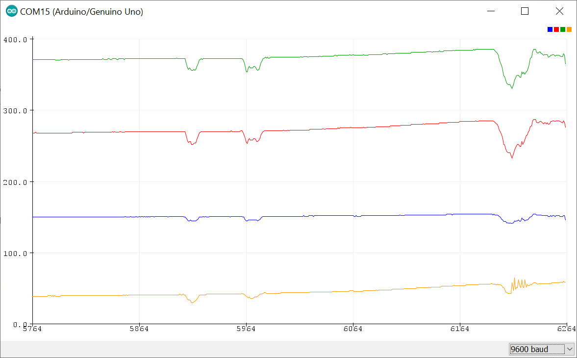
Colors curves shown in the “Serial Plotter”
The connection of the color sensor to the Arduino UNO are the same as explained in the above Connections to an Arduino UNO section.
The LEDs on the Arduino UNO are connected in these pins (through a current limiting resistor):
| PIN | Color |
|---|---|
| 5 | RED |
| 4 | GREEN |
| 3 | BLUE |
| 2 | YELLOW |
Now you can turn on a colored LED in front of the sensor and see the corresponding LED turned on by the Arduino. We have used the 400-point solderable breadboard, some push-buttons and the R/G/B/IR LEDs connected to a 9V battery to make a simple test board.