Artekit AK-LINK-2 USB JTAG
This is the user manual and guide for the AK-LINK-2 USB JTAG board.
Introduction
In this guide we are going to learn about the Artekit AK-LINK-2 JTAG ADAPTER and how to use it with the most known IDEs and debugging software.
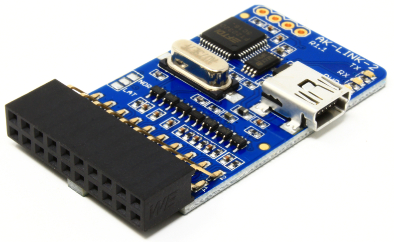
The AK-LINK-2 is a JTAG probe based on the well-known FTDI FT2232D device. AK-LINK-2 is a replacement of our old AK-LINK (retired), widely used with OpenOCD to flashing and debugging a wide range of ARM devices, and also used to program and debug some Lattice FPGA models like the MACHXO2, MACHX03, XP2, ECP3 and ECP5.
Hardware Overview
The AK-LINK-2 board has a 20-pin standard JTAG connector on one side and a strip of 7 utility pins on the other. The following picture and table show the signals you can find in the standard 20-pin JTAG connector.
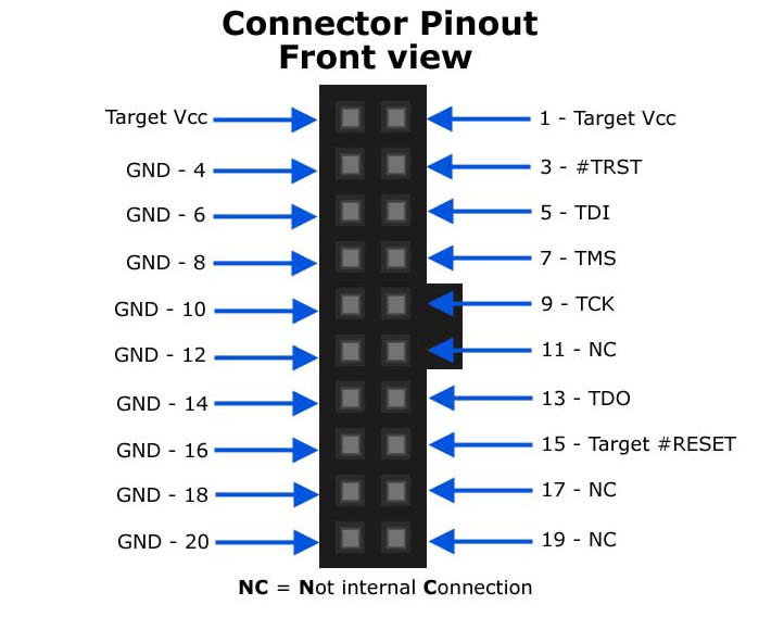
| Pin | Type | Usage |
|---|---|---|
| 1 | IN | Target VCC. Must be connected to the Target VCC |
| 2 | IN | Target VCC. Internally connected to pin 1 |
| 3 | OUT | #TRST JTAG Output (open collector) |
| 4 | PWR | Ground |
| 5 | OUT | TDI JTAG Output |
| 6 | PWR | Ground |
| 7 | I/O | TMS JTAG Output |
| 8 | PWR | Ground |
| 9 | OUT | TCK JTAG Output |
| 10 | PWR | Ground |
| 11 | No internal connection | |
| 12 | PWR | Ground |
| 13 | INP | TDO JTAG Input |
| 14 | PWR | Ground |
| 15 | OUT | Target #RESET output (open collector) |
| 16 | PWR | Ground |
| 17 | No internal connection | |
| 18 | PWR | Ground |
| 19 | No internal connection | |
| 20 | PWR | Ground |
In the AK-LINK-2, all the inputs and outputs signals, to and from the JTAG connector, are buffered. It’s required to connect the pin 1 (Vcc) of the JTAG/SWD connector to the target board Vcc in order to adapt the internal AK-LINK-2 buffers to the target signal levels.
In the top of the board you can see a 4-pin connector as shown in the following picture:
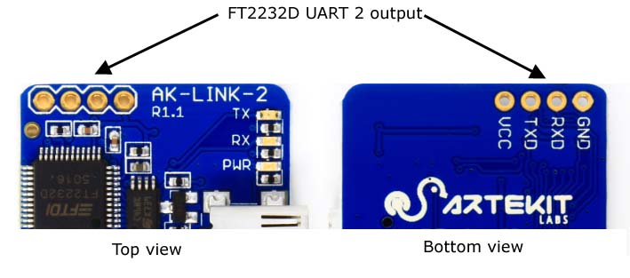
In these pins you can find the second UART channel from the FT2232D chip that can be used as a generic UART. It’s TTL so if you are going to connect it to a PC/MAC remember to use RS232 converter shifter (like the AK-RS232 or through USB with the AK-FT232RL).
The connector pinout signals:
| PIN | Type | USAGE |
|---|---|---|
| VCC | PWR | 3.3V output from the FT2232D internal regulator. Can source maximum 10mA. |
| RXD | INP | RXD input to FT3232D channel 2. |
| TXD | OUT | TXD output from FT2232D channel 2. |
| GND | PWR | Board ground signal. |
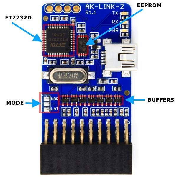
Selection mode: Normal or Lattice
The AK-LINK-2 has two working modes. In one mode the AK-LINK-2 works as a regular JTAG probe (NORMAL mode). In the other mode the AK-LINK-2 can be used to program and debug Lattice’s FPGAs (LATTICE mode)
You can select which mode to use by dropping some solder and joining the required pads as shown in the following picture.
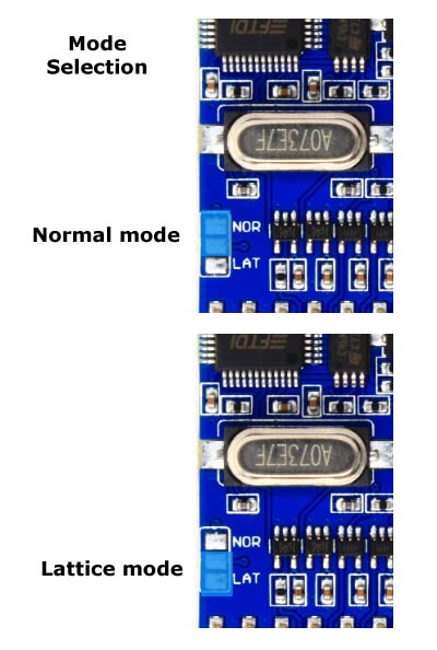
Do not use the NORMAL and LATTICE modes together! This creates a short circuit in the power supply.
At the moment of purchase you can select the default mode and we configure it for you. In case you have purchased an AK-LINK-2 in NORMAL mode and want to put it into LATTICE mode you have to also modify the EEPROM contents so Lattice debug application can interact with the JTAG.
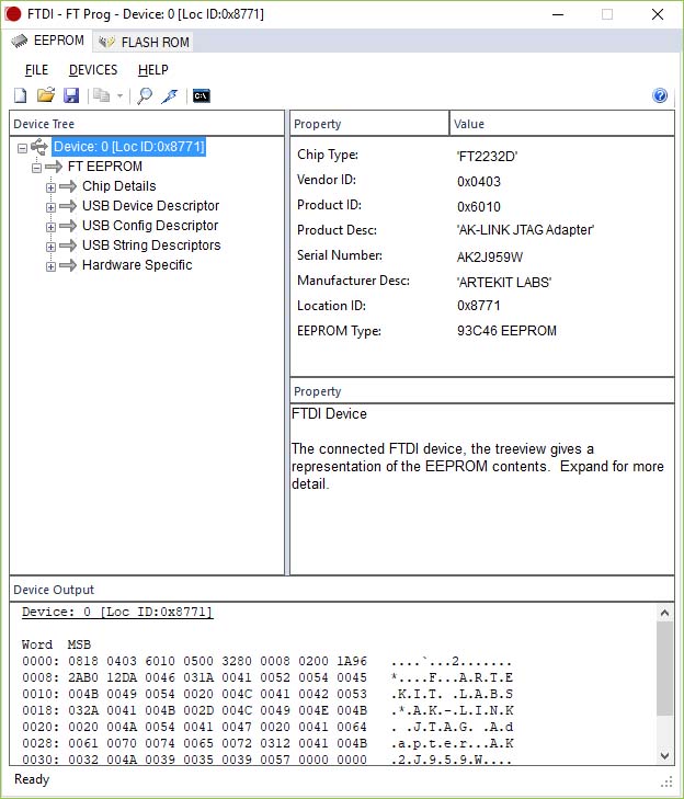
To do this, you must use FTDI’s FT_Prog utility program. You can download it by clicking here.
Connect the AK-LINK-2 to the USB cable and launch the FT_Prog program. Wait some seconds to allow Windows to enumerate the USB devices. From the DEVICES menu select *Scan and Parse”.
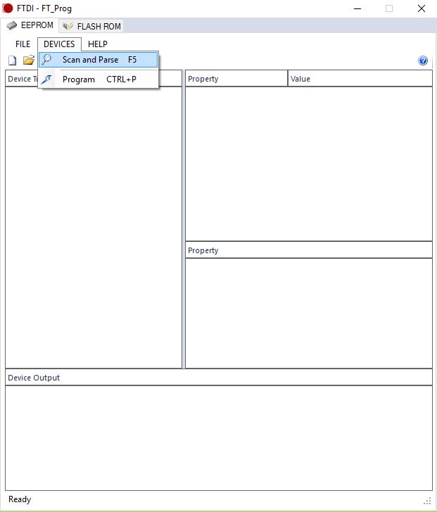
FT_Prog will search for all FTDI devices. We recommend disconnecting all FTDI devices except the AK-LINK-2 to avoid confusion.
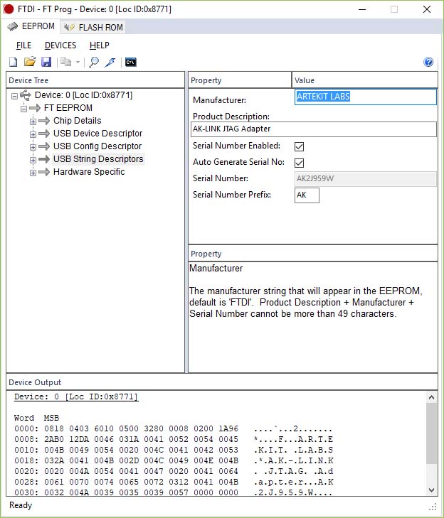
Select USB String Descriptors and change “ARTEKIT LABS” …
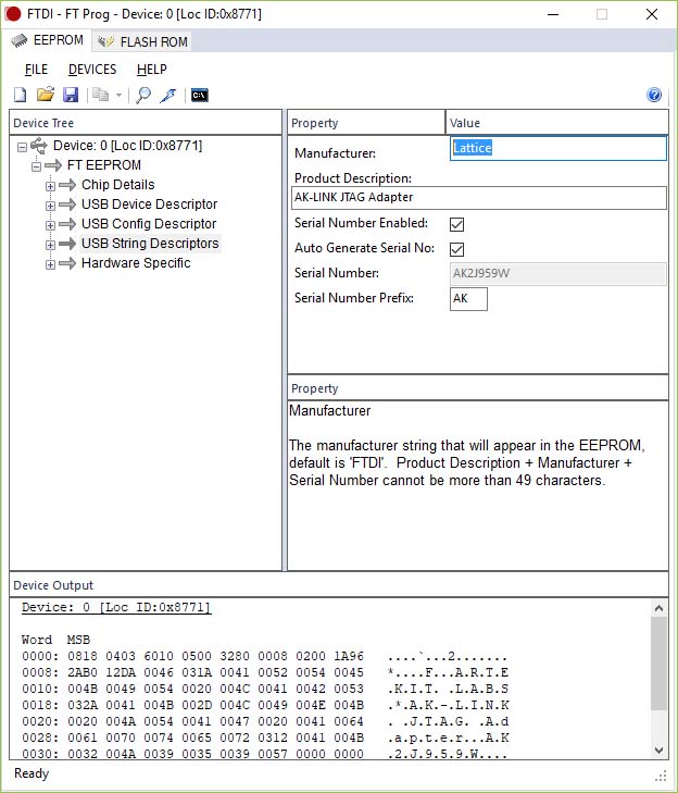
… by “Lattice” in the Manufacturer field. Note that the text is case-sensitive.
Right-click and select Program device. This step writes the new configuration into the EEPROM.
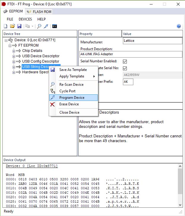
When finished, remember to disconnect and reconnect the AK-LINK-2.
Drivers
The AK-LINK-2 uses the standard drivers freely provided by FTDI. Usually modern operating system already include these drivers, or will be automatically downloaded (i.e. with Windows Update) when the AK-LINK-2 is first attached to the host.
In any other case, you can find here all the drivers for a variety of operating systems.
Using AK-LINK-2 with OpenOCD
To download and install OpenOCD Windows users may want to check the Freddie Chopin webpage for the latest Windows builds. Linux users can download and build it following the instructions on the OpenOCD webpage or with package managers like apt-get.
Once OpenOCD is installed, download and save the ak-link-2.cfg file into the OpenOCD “scripts\interface\ftdi” directory
Here follows a typical OpenOCD command line that connects to a stm32f1x target.
openocd -f interface/ftdi/ak-link-2.cfg -f target/stm32f1x.cfg
If everything works well OpenOCD shows something like the following screen:
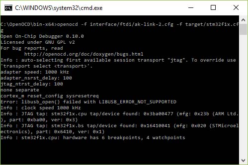
The OpenOCD distribution includes some libusb drivers, but sometimes these drivers are not installed correctly, specially with OpenOCD version 0.10.0. Try with OpenOCD version 0.9.0 or you can try by using the Zadig utility to reinstall the drivers. For more information check the following links:
https://github.com/foss-for-synopsys-dwc-arc-processors/arc_gnu_eclipse/wiki/How-to-Use-OpenOCD-on-Windows https://github.com/marvell-iot/aws_starter_sdk/issues/45