Proffieboard V2.2
Quick guide for the Proffieboard V2.2
The Proffieboard V2.2 has been discontinued in favor of the new Proffieboard V3.9. This page will not be updated and is kept as a reference for the previous version.
Please check the following updated links:
Introduction
The Proffieboard (or just Proffie) has everything you need to boost your electronics props to the next level, with a focus on lightsabers props. It integrates a motion sensor, audio amplifier, power outputs to drive LEDs and LED strips and a micro SD slot. All controlled by a powerful microprocessor.
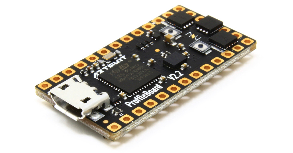
Proffieboard V2.2
In this guide we’ll learn about the Proffie, how to install it, and how to customize the software.
The Proffieboard is a Open Source / Open Hardware project designed by Fredrik Hübinette (a.k.a. Proffezorn). The production of the Proffieboards we will see in this guide (and also in our shop) was curated and tested by Artekit Labs in Italy.
Features
- 100% open-source, you may add any feature you like (GPLv3 license).
- Support for WebUSB for configuration through a browser.
- Thermal Detonator support.
- Blaster support.
- Support for remote control via Bluetooth (with external addon).
- Speedy 32-bit processor makes advanced features like sound filters, synthesizing and mp3 playback possible.
- 16-bit digital output.
- Default sample rate is 44kHz.
- 22kHz and 11kHz samples are supported and upsampled to 44kHz automatically.
- Gapless playback, with 2.5ms cross-fade when you interrupt one sample to go to another.
- Polyphonic playback, currently configured for up to 5 simultaneous samples.
- Support for Ws281X, PL9823, SK68** or Neopixel strings (including RGBW).
- Support for APA102 and dotstar strings.
- Support for arbitrary 1/2/3/4/5/6-color stars/strings.
- Supports segmented string blades (with flash string).
- Multi-blade support for dual and crossguard setups.
- Crystal chamber support.
- Power-level indicator with Neopixel blade.
- OLED PLI display.
- IR sending and receiving.
- MTP support (drag-n-drop files from windows through USB connection).
- POV (persistance of vision) mode.
- Multiple blades (at the same time).
- Accent LEDs. (also implemented as additional “blades”).
- Spoken error messages.
- Easy software updates.
Hardware overview
Pinout
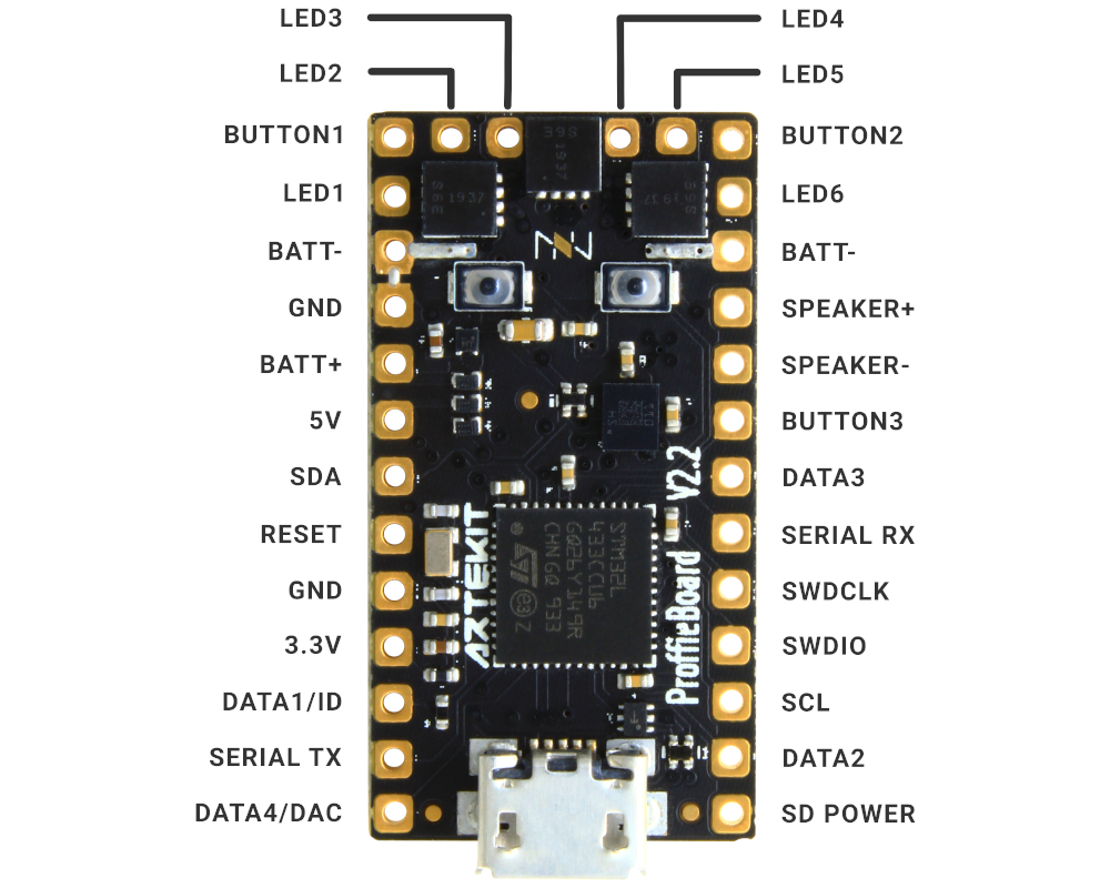
Proffieboard pinout (top view)
- BATT+: connect here the positive of the battery.
- BATT-: connect here the negative of the battery.
- GND: is the ground of the board. Usually connected to the negative of the battery.
- 5V: in this pad you can find 5V to power external peripherals. In most cases can be left unconnected.
- 3.3V: in this pad you can find 3.3V to power external peripherals. In most cases can be left unconnected.
- BUTTON 1, 2 and 3: pads for push-buttons. The quantity of buttons used depends on the configuration. More on this later.
- DATA1 / ID: when using LED strips (Neopixels) this pad is the data output for the LEDs. Otherwise it can measure voltage (through a resistor) to identify the type of blade.
- DATA2, 3, and 4: additional neopixel data outputs.
- LED 1-6: power drivers for the LEDs (Neopixels or high-brightness LEDs). Connect here the negative of the LEDs (and the positive of the LEDs to the positive of the battery).
- SDA and SCL: these pads are connected to the internal I2C bus. Can be used to communicate with external peripherals (like displays). In most cases these pads can be left unconnected.
- SD Power: FET-controlled 3.3v. can be used to power down bluetooth and displays in low-power mode.
- SWDIO and SWDCLK: pad dedicated to debugging and programming the board (with a JTAG). Leave unconnected.
- SPEAKER+ and SPEAKER-: audio output pads. Here you will connect your speaker.
Arduino pin mapping
For those who want to modify the code of the Proffie using the Arduino IDE (more on this later) here follows the pad <–> pin mapping you can use with Arduino functions like digitalRead, digitalWrite, etc.
| Arduino pin | Pad |
|---|---|
| 0 | DATA4/DAC |
| 1 | Data2 |
| 5 | LED5 |
| 6 | LED6 |
| 7 | SDA |
| 8 | Serial RX |
| 9 | Serial TX |
| 10 | LED4 |
| 11 | SD Power |
| 13 | LED1 |
| 16 | DATA1/ID |
| 17 | DATA3 |
| 18 | LED3 |
| 19 | LED2 |
| 21 | BUTTON1 |
| 22 | BUTTON3 |
| 23 | BUTTON2 |
| 25 | SCL |
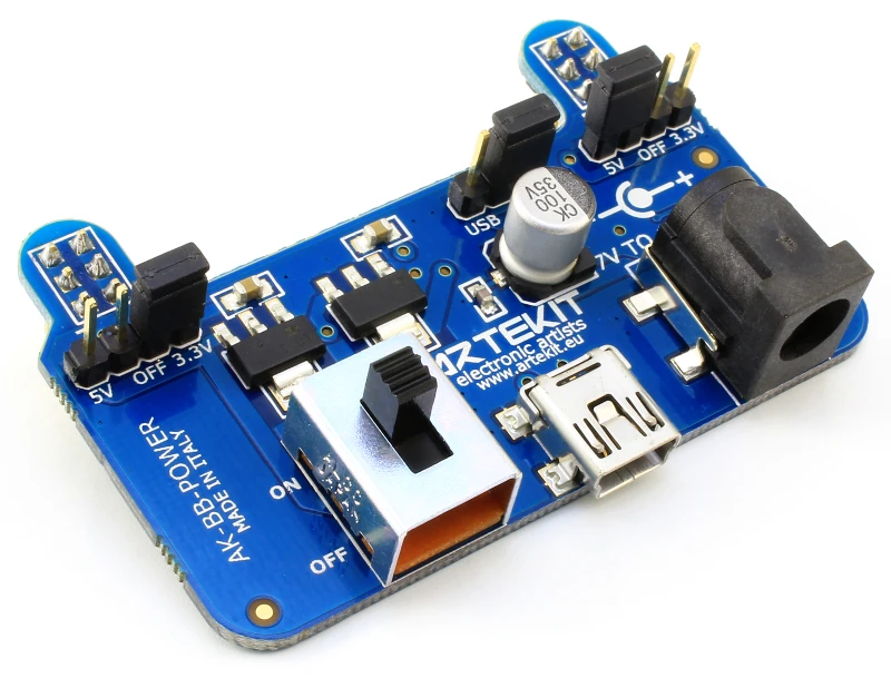
Power supply
The board can be powered from a standard Li-Ion or LiPo battery (like a 18650), accepting a power supply of 2.6V to 4.5V.
There is a polarity protection circuit on board, that prevents damaging the board if the battery poles are connected on the wrong battery pads. This inverse polarity protection is just for the Proffie: it does not protect your LED strips.
LEDs
The Proffie has 6 low-side drivers (MOSFETs) to drive up to 6 high-brightness LEDs (HBLEDs). When using LED strips (Neopixels), these MOSFETs will also control the power supply to the strip.
Using HBLEDs requires a current-limiting resistor that should be connected between the MOSFET output (LED 1, 2, 3, 4, 5, 6 pads) and the LED die. Here is a list of the most common resistor values for a Cree XPE2 RGB LED.
- For the red LED: 1 Ohm
- For the green LED: 0 Ohm (no resistor required)
- For the blue LED: 0.24 Ohm
Looking directly to High-brightness LED can permanently damage the eye. Use with caution.
Speaker
You can use a 4 to 8 Ohm speaker. The Proffie has a Class-D audio amplifier. This means that the audio output signal is digital, and that you can connect the speaker wires without considering the polarity (that is, it doesn’t matter if the negative of the speaker goes to SPEAKER- or SPEAKER+; it will work the same).
Installation
Software
In order to enable the different customizations and configurations of the Proffieboard you will need to install the Arduino IDE and a plugin.
We recommend you to follow the official Proffie Wiki that you can find by clicking this link.
The Arduino IDE and plugin setup is pretty straightforward and it won’t take more than five minutes to install.
Hardware
For installing the Proffie you will need a soldering iron, solder and good wires. We recommend to use of quality wires for connecting the battery and the LEDs. Remember that a wire is a resistor; the thinner the wire, the higher the resistance, and with resistance there is voltage drop. When using thin or cheap wires the effect you will notice is degradation in the audio quality and LEDs not showing the right colors or not working at all. Choose your wires wisely!
The way you will be connecting the board in your lightsaber prop basically depends on the kind of blade you want to use (Neopixels or high-brightness LEDs like the Cree XPE2), quantity of buttons and the use of peripherals like graphic displays. And since the Proffie is super configurable, there are a lot of ways you can connect the board.
For this, Fredrik has prepared a super useful tool that allows you to configure your Proffie installation and shows you how to connect all the components, that we will see in the following section.
Configuration
Click on this link and scroll down until “Configurator”.
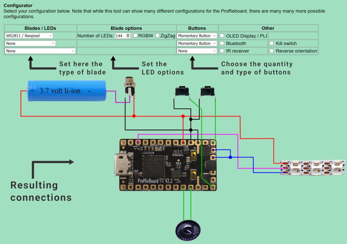
Proffieboard configurator
There you can select the kind of blade you want to use, the quantity and type of buttons, external peripherals, etc. Right under it there is a design showing how to connect the board with said configuration. As easy as it gets.
Once you have decided how to connect your Proffie, notice the text box below the wiring diagram. This is what is called the config file, and is the result of the configuration you have made using the Configurator.
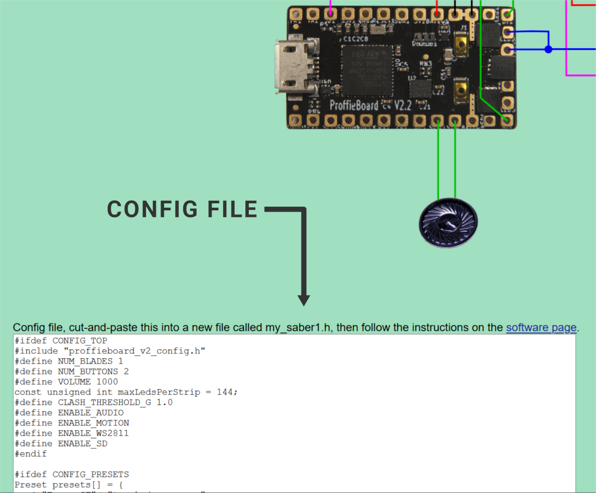
Proffieboard config file
In order to use this config file, you have to transfer it into your Proffie. So let’s get to it:
- Download the latest version of ProffieOS (this is the name of the software that pulls the string inside your Proffie) from this link. At the time of writing this guide, the ProffieOS version is the 4.7.
- Unzip the downloaded file and double-click the ProffieOS.ino file. This will open the ProffieOS project in the Arduino IDE.
- In the Arduino IDE, find this line: #define CONFIG_FILE “config/default_proffieboard_config.h”.
- Replace this line with #define CONFIG_FILE “config/my_config.h”
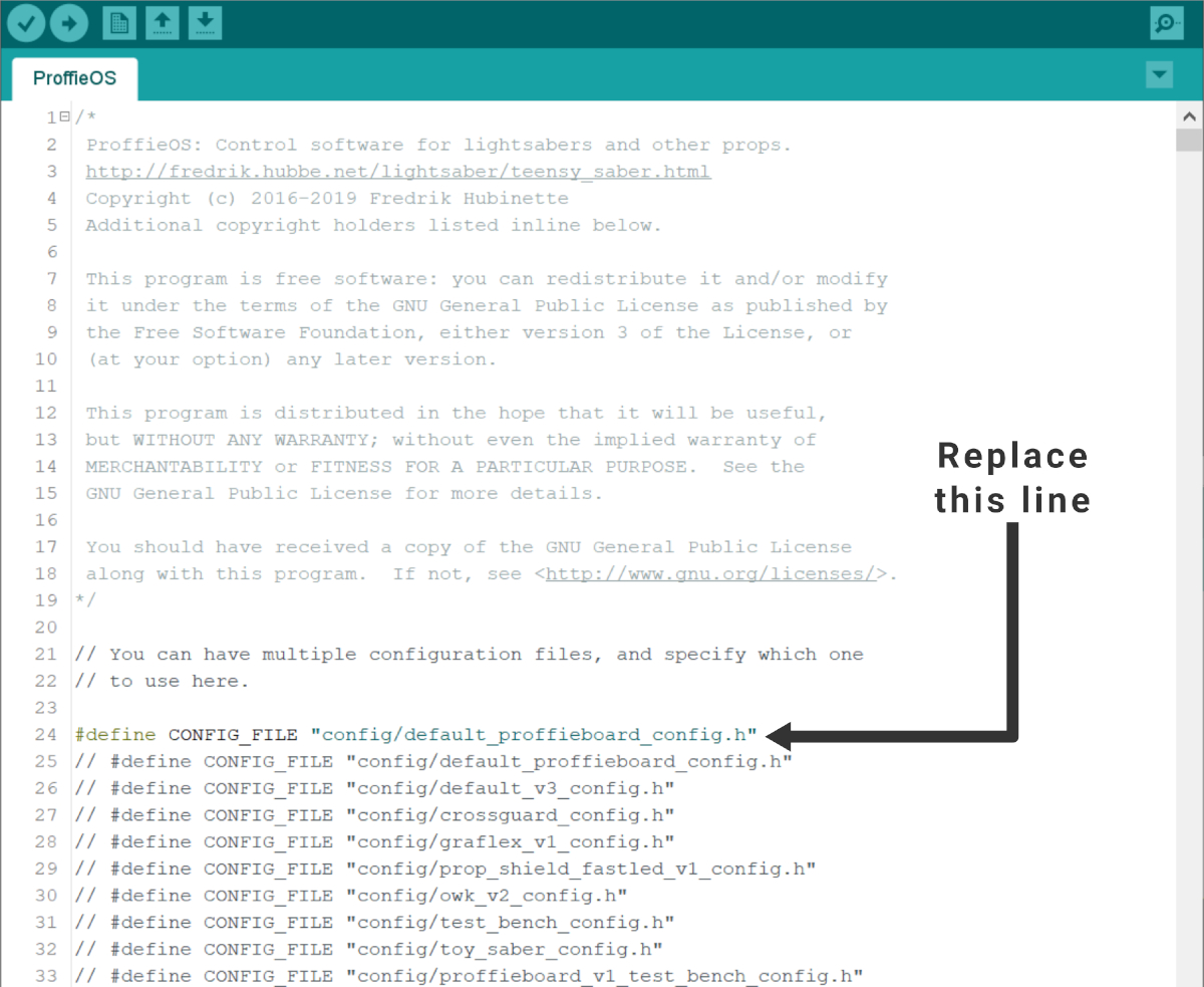
The line to replace in the Arduino IDE
- Now go to the config folder and create a new file called my_config.h
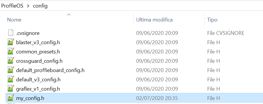
The my_config.h file in the config folder
- Copy the text that was generated by the Configurator (the text box below the wiring diagram) into the my_config.h file you have just created. Save and close the my_config.h file.
- Connect the USB cable into the USB connector of the proffie, Go back to the Arduino IDE and click on download (the right arrow button).
If you want to make adjustments to the configuration, go back to the Configurator, make the changes and then repeat from step 6).
NOTE: the name chosen here (my_config.h) is arbitrary and can be any. Just remember to change the ”#define CONFIG_FILE “config/my_config.h” text to make it point to the correct file. This way, you can have different files with different configurations and chose which one to use by modifying that line.
Customization
There is still more you can do with your Proffie. You can completely customize the look-and-feel of your lightsaber using Presets and Blade Styles.
Styles define the LED effects for your blade, like the color, shimmering, clash and blaster effects and more. You can customize the Style of your blade using the Style Editor or install one of the many community-shared styles.
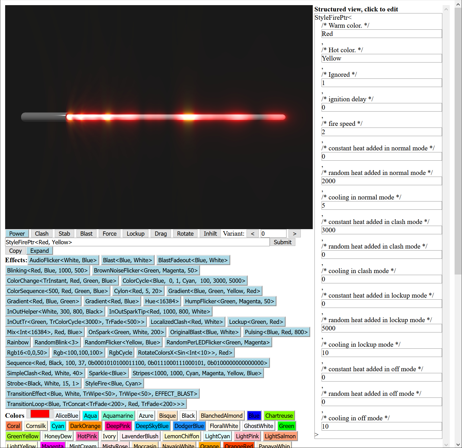
Proffieboard Style Editor
Recommended resources
Here is a list of the resources worth reading while installing the Proffieboard and after. The list comprises official documentation sources and also communities related to the Proffie world.
- Proffieboard product page from Artekit Labs
- Fredrik Hübinette’s Official Proffieboard page
- ProffieOS page
- ProffieOS Wiki (strongly recommended reading)
- Proffieboard hardware (schematics and more)
- Style Editor
- Styles sharing page
- The Rebel Armory Forum provides community help and support
- Open Source Sabers Facebook group