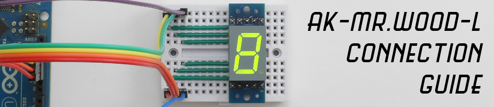
AK-Mr.Wood-L is a little board that features a 7-segment display and a shift register. In this tutorial you will learn how to connect it and how to write code for it. We’ll start with some theory (that you can skip if you know what a shift register is), a basic hardware overview and then how to connect it to an Arduino/microcontroller.

Shift registers are often used to expand the quantity of pins of a microcontroller, or to save some since there is a limited quantity of pins a microcontroller can use as GPIO.
A shift register is basically a device with an 8-bit register (the one that AK-Mr.Wood-L uses is 8-bit, but there are others) and 8 output pins. Every bit in the register matches an output pin, so the output pin status (high-low) depends on a bit value (1 or 0) in the register. These output pins are called Qa, Qb, Qc, Qd, Qe, Qf, Qg, and Qh, and we will say that they are mapped in the register as the bits 0 to 7, respectively.
The shift register has also the SER pin, the SRCLK pin, the RCLK pin and the Qh1 pin.
By moving the SER pin on the shift register, you set a bit value (1 or 0, high or low). By moving the SRCLK pin you insert this bit value into the register. So the sequence is: set the SER pin to the state we want, then move the SRCLK pin from high to low (a pulse). This will “shift-in” the bit into the register.
“Shift-in” means that every bit in the register is moved to the next position (bit 7 takes the value of bit 6, bit 6 takes the value of bit 5, and so on) and that the bit 0 will take the new value we have just put in the SER pin. So, what happens with the value that was on the bit 7? At the end of the “shifting-in” process, you can find the value that was on the bit 7 in the Qh1 pin (and this is what we’ll use to daisy-chain the AK-Mr.Wood-L boards; more on this later).
To fill the entire register we repeat the above eight times. Once you have filled the register we can tell the shift register to transfer those values to the Qa-Qh pins. We do that by moving the RCLK pin from low to high (this is called Latch). After doing this we will see that the Qa-Qh pins reflects the value of the bits in the register.
This type of shift register is called 8-bit serial in, parallel-out shift register: we shift-in bits in a serial way (clock + data) and convert the serial data on parallel signals (output pins).
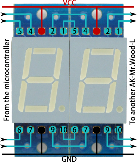
On the top of the board there is the 7-segment display. A 7-segment display is basically 8 LEDs connected with a common cathode or a common anode (the AK-Mr.Wood-L uses a common cathode display).
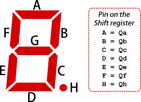
There are 7 LEDs for the segments and a LED for the decimal point. These LEDs are called A, B, C, D, E, F, G and H. Every LED of the display is connected to an output pin of the shift register (through a resistor).
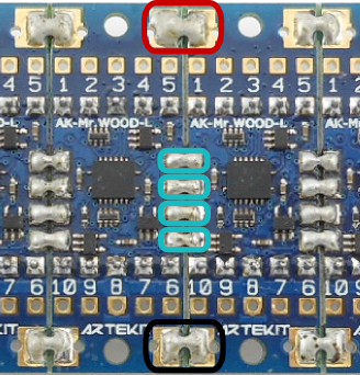
On the back of the board there is the shift register, that has the SER, OE, SRCLK and RCLK signals connected to the pins of the board and to the daisy-chain pads, as follows:
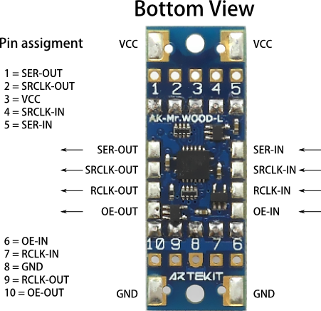
Those pads you see on both sides of the board are used for daisy-chaining. All the pads has an analogue function of a AK-Mr.Wood-L pin (for example, the SER-IN pad is the same signal as the pin 5).
You may notice that for every shift register signal there is an IN and an OUT signal. This is because the AK-Mr.Wood-L has buffers for the pins that are shared when daisy-chaining (to improve signal quality). This means that the signals have a direction, and every signal entering the board has to be through an IN pin.
The SRCLR pin is not available on the AK-Mr.Wood-L.
To use the AK-Mr.Wood-L you need a minimum of 3 pins of the microcontroller, and those are for SER-IN, SRCLK-IN and RCLK-IN. OE-IN pin is optional and you can connect it to GND to keep the shift register always enabled.
In the examples here proposed we will connect all four pins to an Arduino UNO, like this:
| Arduino UNO pin | AK-Mr.Wood-L pin |
| 10 | 6 (OE-IN) |
| 11 | 7 (RCLK-IN) |
| 12 | 5 (SER-IN) |
| 13 | 4 (SRCLK-IN) |
Don’t forget to connect VCC (from 3.3V up to 5V) and GND, that are the AK-Mr.Wood-L pin 3 and 8 respectively.
If you have connected the AK-Mr.Wood-L as described above, you are ready to start writing some code. Open up the Arduino IDE and copy and load the code here below. What you will see is the number 2 blinking in intervals of 500 millisecond.
void setup()
{
 /* Configure the necessary pins as outputs */
 pinMode(10, OUTPUT); /* Output enable (OE-IN) */
 pinMode(11, OUTPUT); /* Latch (RCLK-IN) */
 pinMode(12, OUTPUT); /* Data (SER-IN) */
 pinMode(13, OUTPUT); /* Clock (SRCLK-IN) */

 /* Enable the AK-Mr.Wood-L */
 digitalWrite(10, 0);
}

void loop()
{
 byte number_two = 0x5B;

 /* Put the latch pin low */
 digitalWrite(11, 0);

 /* Shift out a byte into the AK-Mr.Wood-L shift register */
 shiftOut(12, 13, MSBFIRST, number_two);

 /* Put the latch pin high */
 digitalWrite(11, 1);

 delay(500);

 /* Put the latch pin low */
 digitalWrite(11, 0);

 /* Clear the display by filling the shift register with a 0 value */
 shiftOut(12, 13, MSBFIRST, 0);

 /* Put the latch pin high */
 digitalWrite(11, 1);

 delay(500);
}
Easy, right? But there is more. We have prepared a nice library for Arduino that automates most of the tasks, but we will talk about that in our next tutorial.
As mentioned before, the AK-Mr.Wood-L board can be daisy-chained. This allows you to form a larger display while using the same code as with a single display. When daisy-chaining, remember that the data flow (the shifting) happens from left to right, and you have to connect your microcontroller to the leftmost board.
There are two ways of daisy-chaining the AK-Mr.Wood-L: one is using the pins. This way the chaining happens outside the AK-Mr.Wood-L (by the means of wiring the connections). To do that, connect the board in the following way.
| AK-Mr.Wood-L on the left | AK-Mr.Wood-L on the right |
| Pin 1 (SER-OUT) | Pin 5 (SER-IN) |
| Pin 2 (SRCLK-OUT) | Pin 4 (SRCLK-IN) |
| Pin 9 (RCLK-OUT) | Pin 7 (RCLK-IN) |
| Pin 10 (OE-OUT) | Pin 6 (OE-IN) |
The other way of daisy-chaing the AK-Mr.Wood-L is through the pads on the back of the board, by putting some solder between the pads. This will ensure connectivity of the required (IN and OUT) signals to chain several boards. In total you will need to solder 6 pads (GND and VCC, and the 4 signals) to join two boards.
We hope you enjoyed the firsts steps with the AK-Mr.Wood-L. Check out our next tutorial: it’s about the AK-Mr.Wood-library for Arduino.
Have fun!
The Artekit Team.