This article is about LEDs connected in series. We’ll focus in LEDs for LCD backlight, but the content also applies to most strings of serially connected LEDs.
The following illustration represents what could be a typical LCD backlight. The backlight for this example consists in 7 serially connected white LEDs, for a 250 to 350 Cd brightness.
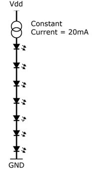
As we have seen in the previous article, each white led (usually) needs a forward voltage of 3.2V and 20mA. So we have multiply 7 x 3.2V to get the necessary 22.4V, to light all the LEDs, and to set the forward current to 20mA.
The first approach seems to be to apply 25V to the LEDs and replace the constant current generator with a resistor to fix the forward current to 20mA. This is done through a 130 Ohm resistor.
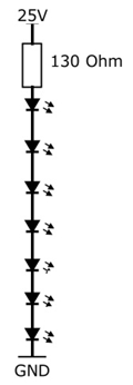
The problem here is to found a 25V power supply; not every circuit we come across has a 25V power supply. Plus, the luminosity will be always fixed to the maximum brightness. So, how do we overcome this problem?
The solution for this problem is found in LEDs drivers, that are a special boost converters and provide constant current for the LEDs.
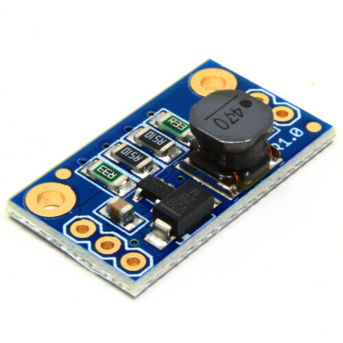
Let’s take for example, the Texas Instruments TPS61165, that is easy to use and understand. The following drawings were taken (and modified a little) from the TPS61165 datasheet.
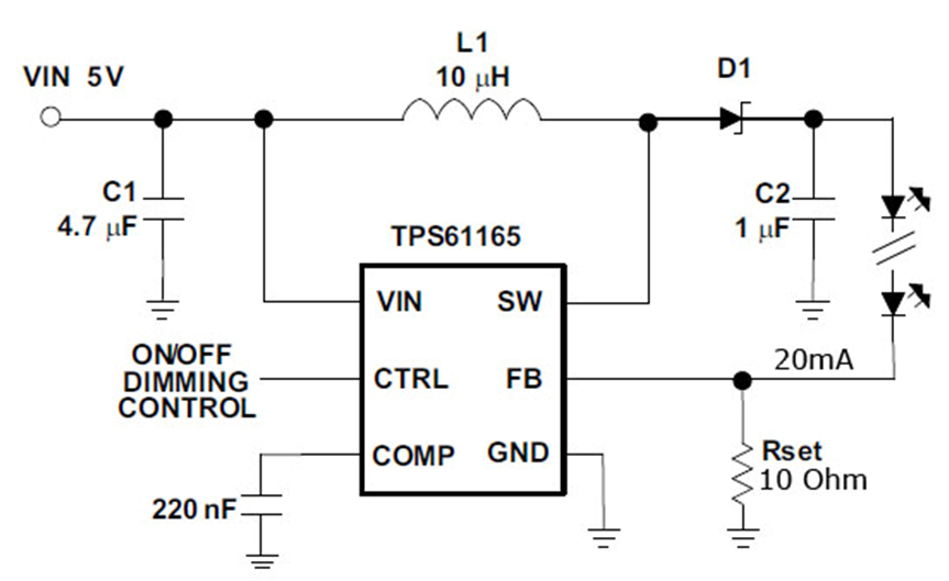
Basically, what the TPS61165 does is to control the voltage supply for the LEDs by sensing the current over the Rset resistor, through the FB (feedback) pin.
When we apply a voltage between 3V and 18V (from our circuit’s main power supply) to the VIN pin, the TPS61165 starts increasing the output voltage on the SW pin. This voltage is applied to the anode of the first LED.
We know that serially connected LEDs will draw the same current as a single LED (in this example, 20mA for white LEDs). As the voltage increases, the current over the Rset resistor increases too. When the voltage over the Rset resistor (and thus on the FB pin) reaches 200mV the TPS61165 stops increasing the voltage on the SW pin, and it remains constant. This 200mV value (of feedback voltage) is a characteristic of the TPS61165.
To reach those 200mV we need to draw current through the Rset resistor, and by applying Ohm’s law we can get the right value for Rset.
So this is what we know: 20mA for the LEDs and 200mV for the FB pin.
Rset = FB voltage / LED current = 0.2V / 0.02A = 10 Ohm
This way, the necessary voltage for the LEDs will be automatically adjusted using only a 5V power supply. If you decide to add more LEDs, the TPS61165 will adjust the voltage automatically.
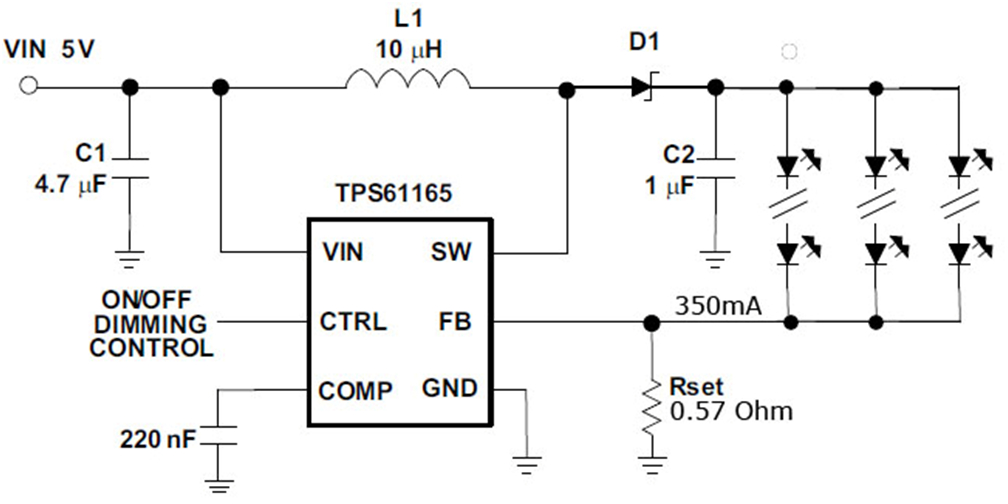
Some high brightness TFT displays use several parallel serially connected LEDs, but the operation theory is the same. We need to simply recalculate Rset to the new LEDs current.
The TPS61165 supports a maximum of 38V on the SW pin and a maximum of 1.2A of LED current. These maximum rating values prevent damages to the IC when an LED is open (broken, burnt), since the current on the FB will drop and the TPS61165 will start to increase the voltage trying to reach the needed 200mV feedback. In this case, the TPS61165 will enter into shutdown mode.
Using the CTRL pin, you can turn ON/OFF the backlight by either applying a PWM signal or by using a single wire, TI proprietary protocol called Easyscale (more details on the datasheet). This allows you to increase or decrease the brightness of the backlight.