LEDs are everywhere. From your keyboard to remote controls. Initially used for indication purposes, now we can see them on big wall screens or illuminating entire rooms. In this quick guide you’ll learn the basics about LEDs and some tips and tricks.
What is an LED?
LED stands for Light Emitting Diode. It’s special diode that emits light by converting electrical energy. It’s made of a semiconductor (called die) that was modified to create a p-n junction (with a process called doping). When an electrical current is applied to the die, electrons pass from the n-side to the p-side of the semiconductor and energy is released in the form of photons. The color of the LED is given by the energy of the released photons (that depends on the material of the semiconductor and the resulting p-n junction). By manipulating the energy of the released photons different light wavelengths can be generated, from infrared light, visible colors to the human eye and ultraviolet.
The electrical symbol of the LED is very similar to a standard diode. 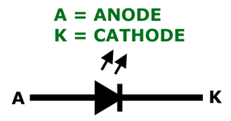 An LED is composed of several parts, but the most important is the die, that characterizes the light intensity and color. The rest of these parts are mostly of mechanical interest, and for holding all the parts together.
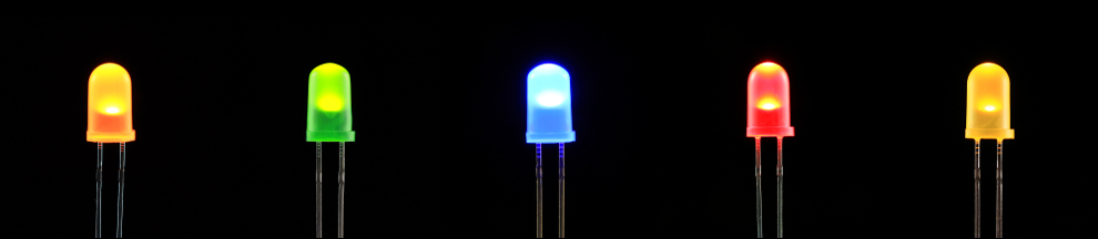
This is a representation of a classic 5mm LED. 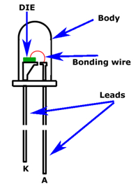 LEDs come in a great variety of sizes and shapes. Like the 5mm here above, 3mm, round, for surface-mounting, etc.
The most common use cases for LEDs are:
- Signaling: for example to show the status of a device, ON/OFF indicators, etc. We’ll be covering this kind of use in this guide.
- Illumination: modern low power LED lamps, automotive lights, etc.
How to use an LED
Polarity
The first thing to look is how to connect an LED. All LEDs have an anode (A) and cathode (K). In the case of the traditional LED (as in non-surface mounting version), they have a long lead and a short lead. The long lead is the anode (where the Vcc side is connected) and the short lead is the cathode (where ground side is connected). Refer to the drawings here above to identify both leads. The good news is that an LED, being a diode, allows the current to flow only in one direction, meaning that if you connect the LED backwards it won’t work, but it surely won’t break.
Current & current-limiting resistors
When connected to a current source, an LED will draw and dissipate as much current there is in the current source. If this happens, the LED will be permanently damaged. For this reason a current-limiting resistor has to be used.
Selecting a resistor for the LED involves some reading of the LED’s datasheet (plus some trial and error). You need to know what it’s called Forward Current and Forward Voltage. Forward Current is the maximum current allowed for the LED and it’s the value the LED will draw when is lit at it’s maximum brightness. Forward Voltage is the minimum and maximum voltage range the LED needs to emit light. This is the voltage measured between the anode and cathode.
To calculate the current-limiting resistor, a little math is needed. For example, to get the most light from a blue LED with a 3.1V Forward Voltage with a 20mA Forward Current, using a 5V power supply, the formula will be (using Ohm’s law).
R = (5V – 3.1V) / 0.02A = 95 Ohm
That’s it. You need a 95 Ohm resistor. You can also use a 100 Ohm resistor, since it’s a standard value and you may not find a 95 Ohm resistor.
Let’s see another example: to get the most light from a red LED with a 2V Forward Voltage with a 3mA Forward Current, using a 5V power supply, the formula will be:
R = (5V – 2V) / 0.003A = 1000 Ohm
In this case you need a 1000 Ohm resistor.
Controlling brightness
Some LEDs used as indicators can be too bright for the purpose, and you may want to dim them a little.
The brightness of the LED can be controlled by increasing or decreasing the current that goes through the LED, and you can do that by varying the resistance value of the resistor connected to it. The formula is very simple: more current, more brightness. Too much current will damage the LED, so it’s always a good thing keep it between the datasheet minimum and maximum values. But you can always push it a little further and test.
Another method for controlling the brightness is by using PWM (pulse-width modulation). Here you’ll need a microcontroller to generate a sequence of pulses (high and low) that will turn the LED on and off, very quickly and almost imperceptible to the human eye.
By turning the LED on and off with the right duty cycle you can create the illusion of light dimming, taking advantage of the persistence of the human eye and the flicker fusion threshold. This is also an interesting way to save battery because the LED spends some time turned OFF, with zero current drain.
This is a widely used technique in electronics, and it has some tricks to be mastered: sometimes you’ll come across a device with an LED and notice that there is something weird with that LED, and this is because the programmer did a poor job driving a good and persistent PWM dimming.
Another thing that you may take in consideration is that LEDs of different colors have different characteristics. The difference can be seen directly from the datasheets, but it’s not always immediate as you may be testing different LEDs and you notice that one color is brighter than another. Usually red, orange and yellow LEDs need from 1.9V to 2.1V to light up. A green or blue LED usually needs 3V to 3.4V and white, violet, purple LEDs need 2.9V to 4.2V.
Tips and tricks: LEDs and microcontrollers
This guide wouldn’t be complete without showing how to connect a LED to a microcontroller. Having a LED connected to fixed 5V in the breadboard won’t take us very far.
We here go beyond the fact that connecting an LED to the Arduino works out of the box. And it’s OK to accomplish that. Now let focus as if we have to start from scratch on a new microcontroller.
Calculating the resistor
For this example we will be using a red LED with a Forward Current of 3mA and a Forward Voltage of 2V, connected to a microcontroller powered with 5V. The microcontroller will output 5V from its GPIO pins.
The first thing to do is to know the characteristics of pin we want to connect our LED. We need to know how much current we can source from it. For example, if we take the popular ATmega328 datasheet, we can search for the IOL and IOH parameters (you can find those parameters on other microcontrollers as well, even with the same name).
These parameters are (click to enlarge):
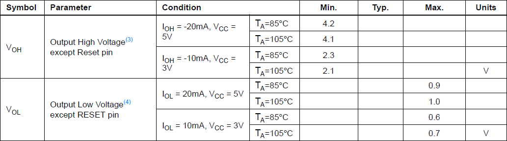
IOL = 20 mA, Vcc= 5V
IOH = -20mA, Vcc = 5V
What these parameter mean is that at 5V an IO pin can source up to 20mA when the pin is high, and that it can sink 20mA when the pin is low. Another important parameter is that the pin will output at minimum 4.2V when the pin is high. We’ll take that into consideration to calculate the value of the current-limiting resistor.
So, to light up our red LED we need a resistor of: (4.1V – 2V) / 0.003A = 700 Ohm.
Choosing the right logic
Nobody says that an LED has to be always lit up with a logic 1 (active-high logic). The alternative is to light the LED up with a logic 0 (active-low logic).
For instance, you may know that in most of modern microcontrollers you can choose how an output pin may behave. It can be a Push Pull or Open Drain output pin.
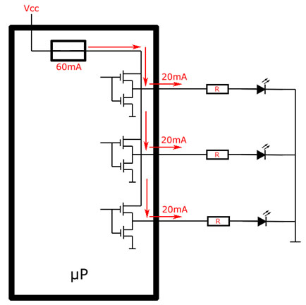
When using Push Pull outputs with active-high logic, you’ll end up with something like this:
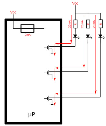
When using Open Drain outputs with active-low logic, you’ll end up with something like the following. Note that with this configuration you need to put the output LOW to turn the LED on.
If you microcontroller IOH parameter is enough to source the LED current, you can use the Active High (Push-Pull) mode. If not, you can try with the Active Low (Open-Drain) mode, but you must not exceed the IOL parameter.
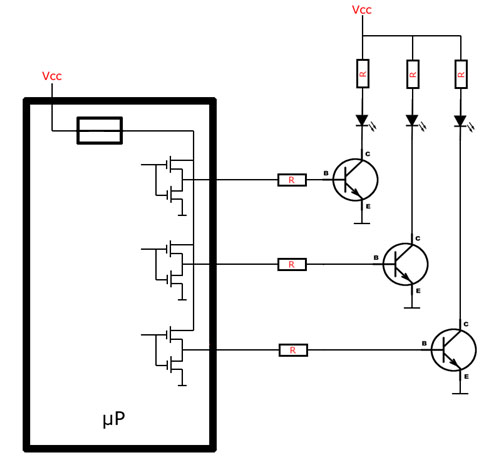
When open drain is not available
If you are on the limits or beyond the current an output can source, you can use NPN transistors and drive those with active high logic from an output of the microcontroller, as in the following picture.
LEDs in series
You can connect LEDs in series. The trick would be that you have to source current below or equal to the maximum current allowed for the less current-consuming LED. For example if you connect in series a 25mA blue LED with a 15mA red LED, the sourced current has to be equal or less than 15 mA.
Another thing to keep in mind is that every LED has a Forward Voltage drop (as explained before), so the voltage source has to be at least equal to the sum of the Forward Voltage Drop of every LED. For example: if you have a 3.4V blue LED and a 2V red LED, the series will need a voltage source of at least 5.4V.
LEDs in parallel
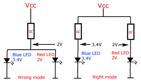
When connecting LEDs in parallel through a single resistor, the resistor has to be calculated based on the sum of the current of every LED.
If you use LEDs of different colors, keep in mind that those may have different characteristics, and a single resistor may not fit every possibility. You may notice that when connecting in parallel a red LED and a blue LED through a single resistor, the red LED lights up but the blue LED doesn’t. In this case use different resistors for the different colors you may have in your circuit.
Conclusion and final tip
If you have a lot of LEDs and need a fast way to calculate resistors, you can use one of many online tools. A nice one is this, that generates a picture of the resulting resistor (with the resistor colors).
We hope you have enjoyed reading this guide, and ask here or in the forum if you have questions.
The Artekit Team.