Thanks to Laurence Vanhelsuwe, of Software Pearls, for submitting this article.
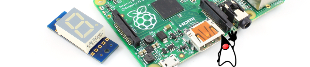
We’ve seen how to drive one or more AK-Mr.Wood-L modules via an Arduino, but not everyone uses Arduinos; another very popular development platform today is the Raspberry Pi.
This blog post will take a different tack, and uses a Raspberry Pi (Model A) programmed in Java to display integer values on a chain of MrWoods boards, in this case 5 modules for a maximum 5-digit display (maximum value 99999).
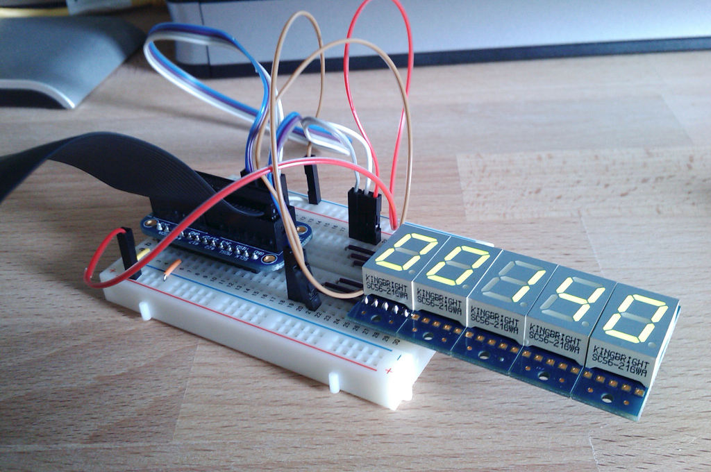
Five chained Mr.Wood boards plus Breadboard wiring
Before we dive in, we need to make the following assumptions about the components you have, and the knowledge you’ll need to comfortably follow this article.
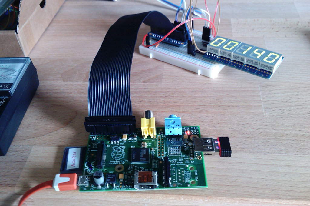
You will need a Raspberry Pi (A or B) with Java (J2SE) installed. We used Java version 1.7.0 (update 40), which came pre-installed on the recently bought SD card featuring the official Raspberry NOOBS package. Older Raspberry distributions did not come with Java pre-installed, so you may have to Google for any number of detailed installation procedures. Next, you will need the Pi4J library installed and ready to rock. This needs to be installed manually (the official site has all the instructions), as NOOBS hasn’t yet gotten round to also having this pre-installed. On the hardware front, you will almost definitely want to use some breadboard, and maybe a GPIO breakout board to create a clean bridge between your Raspberry and breadboard. As you can see from the picture, I used Adafruit’s well-known Cobbler product.
Raspberry Pi A connected to breadboard via Cobbler
The subjects you will need to understand to get the most of the following, are: controlling your Raspberry via SSH, binary and decimal number system, ASCII encoding and the basics of Java programming.
With the assumptions out of the way, let’s dive in.
Divide and Conquer
The Mr.Wood module consists of two logical parts which we need to tackle individually in Java to obtain some clean, reusable and maintainable code: a 7-segment display, and an 8-bit shift register. Given that Artekit also has a seperate, stand-alone 8-bit shift register breakout board (the AK-SN74LV595), it pays to develop a Java class that deals purely with the shift register, and completely ignore the display for the time being. That way, half of the effort of getting the MrWoods under control may be reused in the future by any other projects requiring the use of (SN74LV595-compatible) shift registers.
The TI SN74LV595 8-bit Serial Shift Register
Before writing any code, it is a worthwhile investment of your time to have a good look at the official Texas Instruments data sheet for the chip; you can find the PDF here.
Note that the shift register chip doesn’t care how you use it: you may shift in a single bit, and latch. Or you may shift in a whole byte, and latch. Or you may do things a nibble at a time, the chip definitely does not assume you’re shifting in bytes at a time, and doesn’t recognize any byte boundaries.
The 8-bit shift register, which we’ll call the 595 from now on, uses three main digital control signals to coordinate the bit shifting process: SER, SRCLK and RCLK.
What we need to do in Java to talk to the register, is to use three Pi4J GpioPinDigitalOutput and drive them appropriately. The shift register specification explains (on page 4, Timing Diagram) how a single bit is shifted in: you place the bit on the SER line (i.e. you set it high or low, to represent a ‘1’ or ‘0’, respectively), and then you pulse the SRCLK line, effectively telling the chip “grab my bit, and get ready for the next one”. This process is typically repeated 8 times to fill the shift register with one byte, which is then held, or latched, on the 8 parallel output pins, following a latch command.
The MrWood module can be powered by either 3.3V or 5V, so to minimise the chances that the Raspberry buckles at its knees when displaing the 88888 “all-LEDs lit” value, and hence drawing the most current, we’ve chosen to hook up the display cascade to one of the 3.3V pins of the Rpi’s connector.
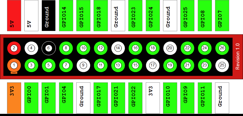
Here’s a reminder of the Raspberry’s GPIO connector pin assignments (note we’re talking about the A or B connector, not the newer 40-pin connector of the B+):
Raspberry Pi A/B GPIO connector pin assignments
The Pi4J documentation labours the point that the API does not follow the names of the official pins, because it, quite sensibly, expects the Raspberry connector(s) to evolve over time. In other words, anyone using Pi4J needs to use connector version-independent pin names.
Our original Arduino-MrWood article explains in detail how to hook up the control signals (SER, RCLK and SRCLK) of the first MrWood to your microcontroller. In our case, we’ve picked (Pi4J pins) GPIO-05, GPIO-06 and GPIO-04, respectively.
The 595 register’s parallel pins are called QA-QH, and not B0-B7, for example. In other words, the pin names do not strongly suggest your hardware design should put the least significant bit in first, or last. This means that the software needs to respect the bit assignments that the hardware designer decided, when physically wiring the QA-QH pins to the rest of a circuit (in our case, the 7-segment display). Concretely, the software needs to be able to shift a byte into the register least significant bit first, or most significant bit first.
The first class we’ll present is rather cryptically called SN74LV595, the shift register’s product name:
package com.softwarepearls.apps.hardware.raspberry.artekit.shiftreg;

import com.pi4j.io.gpio.GpioPinDigitalOutput;

/**
 * Texas Instruments 8-Bit Shift Register.
 * <P>
 * <P>
 * Requires three control lines:
 * <UL>
 * <LI>SER (the shifted-in bit)
 * <LI>SRCLK (the clock signal ordering a bit to shift in)
 * <LI>RCLK (the value latch clock signal ordering the shifted bits to be put on
 * the output)
 * </UL>
 */
public final class SN74LV595 {

	private final GpioPinDigitalOutput ser;
	private final GpioPinDigitalOutput rclk;
	private final GpioPinDigitalOutput srclk;

	/**
	 * Constructor.
	 *
	 * @param ser GPIO pin wired to the SER input
	 * @param srclk GPIO pin wired to the SRCLK (SER CLOCK) input
	 * @param rclk GPIO pin wired to the RCLK (LATCH) input
	 */
	public SN74LV595(final GpioPinDigitalOutput ser, final GpioPinDigitalOutput srclk, final GpioPinDigitalOutput rclk) {

		this.ser = ser;
		this.srclk = srclk;
		this.rclk = rclk;

		ser.low();
		srclk.low();
		rclk.low();
	}

	/**
	 * Shift the given byte (8 bits) out to the register, LSb first. This does
	 * NOT latch the bits.
	 *
	 * @param b any byte
	 */
	public void shiftOutLeastSignificantBitsFirst(final byte b) {

		byte bits = b;
		for (int i = 0; i < 8; i++) {

			// set SER
			if ((bits & 0x01) == 1) {
				ser.high();
			} else {
				ser.low();
			}
			srclk.high();
			srclk.low();

			bits >>= 1;
		}
	}

	/**
	 * Shift the given byte (8 bits) out to the register, MSb first. This does
	 * NOT latch the bits.
	 *
	 * @param b any byte
	 */
	public void shiftOutMostSignificantBitsFirst(final byte b) {

		byte bits = b;
		for (int i = 0; i < 8; i++) {

			// set SER
			if ((bits & 0x80) != 0) {
				ser.high();
			} else {
				ser.low();
			}
			srclk.high();
			srclk.low();

			bits <<= 1;
		}
	}

	/**
	 * Latch whatever bit sequence has been shifted in.
	 */
	public void latchBits() {

		rclk.high();
		rclk.low();
	}

	@Override
	public String toString() {

		return getClass().getSimpleName() + "[SER:" + ser + ", SRCLK:" + srclk + ". RCLK:" + rclk + "]";
	}
}
The class has a simple structure: 3 fields to hold references to the GPIO pins, a constructor and 3 core function methods. Let’s start with the constructor: it takes three Pi4J GpioPinDigitalOutput which point to the Raspberry Pi pins you chose to connect to the Mr. Wood. Be careful not to make mistakes when listing those pins, as the compiler will not be able to spot any typos! The constructor just copies the three references, and then sets all three pins to low (0).
Next in our SN74LV595 class there is the shiftOutLeastSignificantBitsFirst() method. The method takes a single byte, and loops over every bit to shift it out to the shift register. As the method name says, least significant bit first, so the method uses Java’s shift-right operator >> to align each bit with bit 0 so that it can be sent to the hardware (it’s kind of amusing to think that Java is shifting bits out, while the register is shifting them in). The method only drives the SER and SRCLK lines, since we don’t want to perform the latching just yet. To latch the bits we’ve shifted out (or in, depending on your viewpoint), we’ve got a separate little method: latchBits(). This method pulses the RCLK line with a high()/low() pair of calls.
Finally, I almost always write toString() overrides in my classes, so that’s the last method in this class.
While I didn’t have any Artekit AK-SN74LV595 (the stand alone 8-bit shift register) to test this class out with, I’m confident it should be perfectly usable to control that breakout board too.
But today we’re aiming to get some Mr. Wood’s all lit up, so let’s now proceed to the display part of the challenge.
Rendering Digits on a 7-Segment LED Display
The Mr.Wood display is an industry-standard 7-segment LED display, with decimal point LED. These LEDs have documented names A-G plus H for the decimal dot. In the remainder of this article, we won’t deal with the decimal dot, since we’ll only show the rendering of integer values.
Before we delve into any mechanics, let’s just see the source, for our second class called MrWood:
package com.softwarepearls.apps.hardware.raspberry.artekit.mrwood;

import com.pi4j.io.gpio.*;
import com.softwarepearls.apps.hardware.raspberry.artekit.shiftreg.SN74LV595;

/****************************************************************************
 * AK-MrWood-L. One or more 7-segment LED display(s) combined with Texas
 * Instruments 8-Bit Shift Register. Can be daisy-chained to form multi-digit
 * displays.
 * <P>
 * Requires same 3 control lines as a plain shift register (SER, SRCLK, RCLK).
 * <UL>
 * <LI>SER (the shifted-in bit, most significant bit first)
 * <LI>SRCLK (the clock signal ordering a bit to shift in)
 * <LI>RCLK (the value latch clock signal ordering the shifted bits to be put on
 * the output)
 * </UL>
 *****************************************************************************/
public final class MrWood {

	// The LED segment codes A-G are industry-standard (i.e. clockwise starting
	// from top horizontal)
	private static final String[] DIGIT_SEGMENTS_LUT = {
			"ABCDEF",// 0
			"BC",// 1
			"ABGED",// 2
			"ABGCD", // 3
			"FGBC", // 4
			"AFGCD", // 5
			"FEDCG", // 6
			"ABC", // 7
			"ABCDEFG", // 8
			"ABCFG", // 9
			"", // (blank)
	};

	private static final byte[] DIGIT_SEGMENT_BITS_LUT = new byte[DIGIT_SEGMENTS_LUT.length];

	private final SN74LV595 shiftRegister;

	private final int numDigits;

	static {
		initSegmentsLUT();
	}

	private static void initSegmentsLUT() {

		final int numDigits = DIGIT_SEGMENTS_LUT.length;
		for (int digit = 0; digit < numDigits; digit++) {
			final String segmentCodes = DIGIT_SEGMENTS_LUT[digit];
			final int numSegments = segmentCodes.length();
			byte segmentBits = 0;
			for (int segment = 0; segment < numSegments; segment++) {
				final char segmentCode = segmentCodes.charAt(segment);
				final int bitNumber = segmentCode - 'A';
				segmentBits |= 1 << bitNumber;
			}
			DIGIT_SEGMENT_BITS_LUT[digit] = segmentBits;
		}
	}

	/**
	 * Constructor. Use to control single digit display.
	 *
	 * @param ser
	 * @param srclk
	 * @param rclk
	 */
	public MrWood(final GpioPinDigitalOutput ser, final GpioPinDigitalOutput srclk, final GpioPinDigitalOutput rclk) {

		this(1, ser, srclk, rclk);
	}

	/**
	 * Constructor.
	 *
	 * @param numDigits
	 * @param ser
	 * @param srclk
	 * @param rclk
	 */
	public MrWood(final int numDigits, final GpioPinDigitalOutput ser, final GpioPinDigitalOutput srclk, final GpioPinDigitalOutput rclk) {

		this.numDigits = numDigits;
		shiftRegister = new SN74LV595(ser, srclk, rclk);
	}

	/**
	 * Display the integer value on the MrWood chain, right-aligned.
	 *
	 * @param value any n-digit value (where n is the number of MrWood displays)
	 */
	public void show(final int value) {

		final String digits = Integer.toString(value);
		final int digitsLength = digits.length();
		if (digitsLength > numDigits) {
			throw new IllegalArgumentException("Your value, " + value + ", will not display in only " + numDigits + " digits.");
		}

		int accumulator = value;
		for (int i = 0; i < numDigits; i++) {
			shiftDigitOut(accumulator % 10);
			accumulator = accumulator / 10;
		}
		shiftRegister.latchBits();
	}

	public void shiftDigitOut(final int digit) {

		final byte segmentBits = DIGIT_SEGMENT_BITS_LUT[digit % 10];

		shiftRegister.shiftOutMostSignificantBitsFirst(segmentBits);
	}

	public static void delay(final long millis) {
		try {
			Thread.sleep(millis);
		}
		catch (final InterruptedException ignored) {
			;
		}
	}

	public static void main(final String[] args) {

		final GpioController gpioController = GpioFactory.getInstance();

		final GpioPinDigitalOutput ser = gpioController.provisionDigitalOutputPin(RaspiPin.GPIO_05);
		final GpioPinDigitalOutput srclk = gpioController.provisionDigitalOutputPin(RaspiPin.GPIO_06);
		final GpioPinDigitalOutput rclk = gpioController.provisionDigitalOutputPin(RaspiPin.GPIO_04);

		final MrWood display = new MrWood(5, ser, srclk, rclk);

		int start = 9999;
		long delay = 200;
		if (args.length > 0) {
			start = Integer.parseInt(args[0]);
			delay = Integer.parseInt(args[1]);
		}

		int counter = start;
		while (counter >= 0) {
			display.show(counter--);
			delay(delay);
		}
	}
}
Displaying a single digit requires the switching on of the correct LEDs to form the digit. The approach I’ve taken is to first describe each digit, starting with digit 0, by enumerating the necessary LED segment names in a String. That gives us a very readable, initial look-up table:
But Strings are no good to Mr.Wood, it needs bits. Eight bits per digit, with bit 0 switching on the A segment, bit 1 the B segment, and so on. So our MrWood class converts the textual “readable” look-up table into a proper bits-based look-up table called DIGIT_SEGMENT_BITS_LUT. This conversion is done once, when the class is loaded and its static initialisation block is executed. The logic for the code won’t be explained here as it is pretty trivial and incidental.
The next class member is far more interesting: we declare a field called shiftRegister, of type SN54LV595. Via this field, we’ll be able to delegate all the necessary low-level hardware bit banging. The remainder of the MrWood class only deals with matters of decimal digits, so it is a much higher-level class.
The MrWood class has two constructors, both of which taking exactly the same three GpioPinDigitalOutput parameters as our SN54LV595 class did. The second constructor takes an additional numberOfDigits parameter, which the first constructor passes as a default of 1 (to display single digit integers). The 2nd constructor is the real constructor, and it does little more than to instantiate a 595 shift register.
Why not instantiate a shift register per digit, since that’s how the Mr.Wood boards are physically constructed? Well, due to the chaining of Mr.Wood modules, we’re actually only concerned about the first shift register in the first display. All the other shift registers are “secondary” since they are automatically fed all the bits that shift out, as any bits are shifted in at the head (physically, at the left side of a chain of displays).
Now we come to the guts of the MrWood class: the show(int n) method. Here we use a similar “extract-and-shift” logic to our earlier bit shifting-out logic in the SN74LV595 class, but at the decimal digit level: we’re shifting out one (decimal!) digit at a time. Instead of using Java’s shift operators, here we need modulo 10 (“% 10”) and integer division by ten, for the extract and shift operations, respectively.
Shifting a single decimal digit out to the first Mr.Wood in your display chain is as simple as looking up the previously calculated bit pattern for the digit, and asking the shift register to shift out that 8-bit pattern. But here we’re faced with the hardware shift register’s “don’t care” attitude towards endianess: to know whether the byte needs to be shifted out most significant bit first, or least significant bit first, requires you to know how the 595 hardware shift register is wired to the A-G LED segments. In the case of a Mr.Wood, the wiring requires shifting out most significant bit first, so that the correct bits end up switching on “their” segments.
Once all digits have been shifted out, and only then, do we latch the bits (or digits) in place. Remark how this latching is deliberately not done at the end of each digit, to avoid any flicker which otherwise occurs. Also note that we’re really shifting a whole train of 5 x 8 = 40 bits into a virtual 40-bit shift register, and then latching that 40-bit value.
Demo time
Finally, the MrWood class comes with a bit of demonstration code in the form of a static main() allowing you to invoke the class from the command line to play with the display. The command line arguments are the starting count (max 99999), and a delay in milliseconds between counter decrements. The result is a variable speed countdown effect, similar to those used in James Bond movies.
To run the MrWood class on your Raspberry Pi, you may take any number of approaches to transfer the classes to your Raspberry, and then invoke the class at the command line. Personally, I develop on an Apple iMac, and then use a script to bundle all the classes, including the Pi4J classes, into a single JAR, and then copy the JAR across to the Rpi using SSH.
As this article shows, driving one or more Mr.Wood boards using the Raspberry Pi programmed in Java, with a little help of the Pi4J library, is easy. The board’s clever hardware design cuts down on the cost of needing lots of GPIO pins to create a functioning circuit, and the Pi4J API trivial use of the high() and low() methods on GpioPinDigitalOutput made the software side a comparable exercise in simplicity.
Click here to download the source code for both JAVA classes.
This website uses cookies so that we can provide you with the best user experience possible. Cookie information is stored in your browser and performs functions such as recognising you when you return to our website and helping our team to understand which sections of the website you find most interesting and useful.
You can adjust all of your cookie settings by navigating the tabs on the left hand side.
Strictly Necessary Cookie should be enabled at all times so that we can save your preferences for cookie settings.
If you disable this cookie, we will not be able to save your preferences. This means that every time you visit this website you will need to enable or disable cookies again.


2 Responses
Can anyone tell me exactly how much a Mr.Wood consumes when all LEDs are lit, and powered with 5V ?
Hi.
It should be around 80mA per Mr.Wood, with all the LEDs lit.