In this quick guide I will show some tips on how to hand-solder SMT components (precisely, a 36-pin QFN STM32) to a DIP adapter.
Introduction
If you are into electronics prototyping, I am sure you’ve come across a situation where you find a component that perfectly fits your design/project and everything goes well. Then you realize that the component only comes in an SMT package.
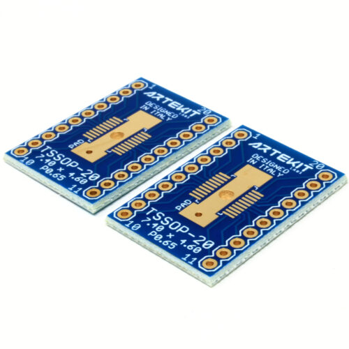
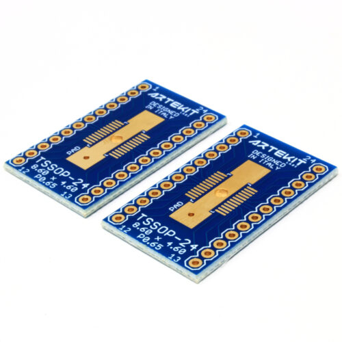
There are a number of ways to overcome the problem. One of them is by using an SMT adapter board.
These definitely are personal tips, that I have used for many years and I feel comfortable with. Of course, this is not the definitive way to do this, but I found this is a quick and reliable method.
We will need the following tools:
- A solder iron with a 0.5mm tip or similar.
- Solder Wick, better of size #1, but you can use a larger measure too.
- Solder flux, in a pen or liquid. We use liquid in this case, but the pen is also OK.
- a little brush (if you use liquid flux).
- Solder, width 0.5mm or less.
- Tweezers
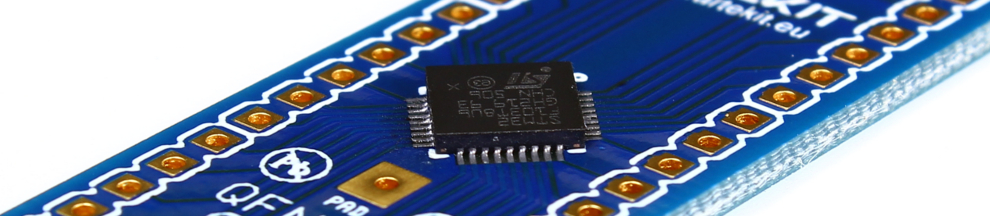
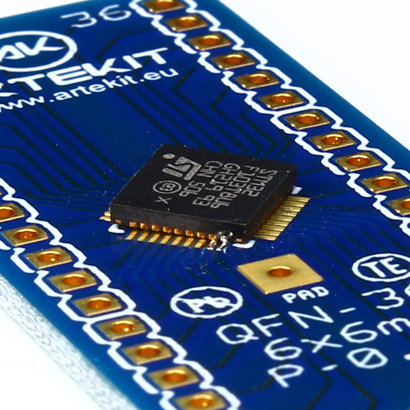
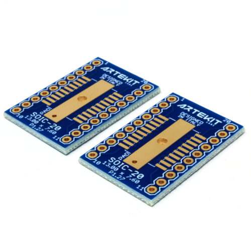
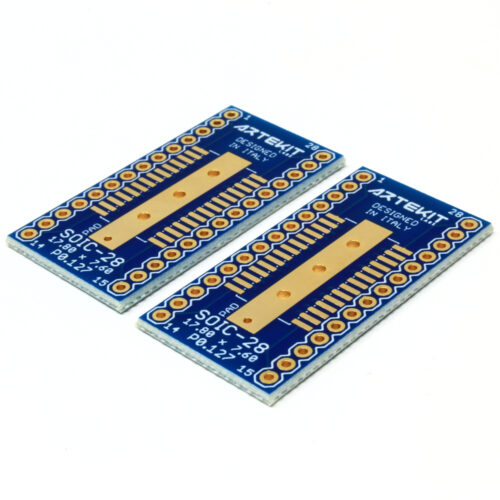
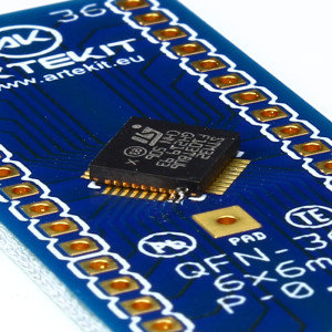
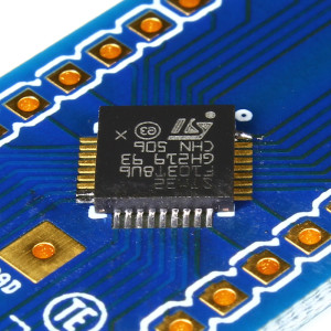
We are going to solder an STM32F103T8U6, QFN-36 package, pin pitch 0.5mm on one of our QFN-36 to DIP Adapter. Even if this guide is about soldering a QFN component, the tips shown here can also be applied to other SMT package types.
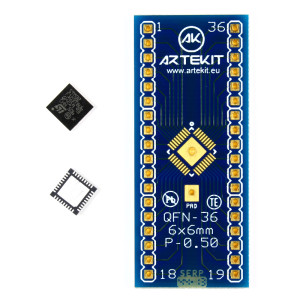
QFN stands for Quad Flat No-Leads. This means the IC has no leads and comes in a flat shape with pads on its four sides, on the bottom. One may believe that this package is harder to solder, but I think it’s easier than soldering TQPF-like packages. With TQPF packages, some (unavoidable) shorcircuits are harder to remove, and yes, you may get a lot of shorcircuits when manually soldering SMT components. The trick is to know how to remove them.
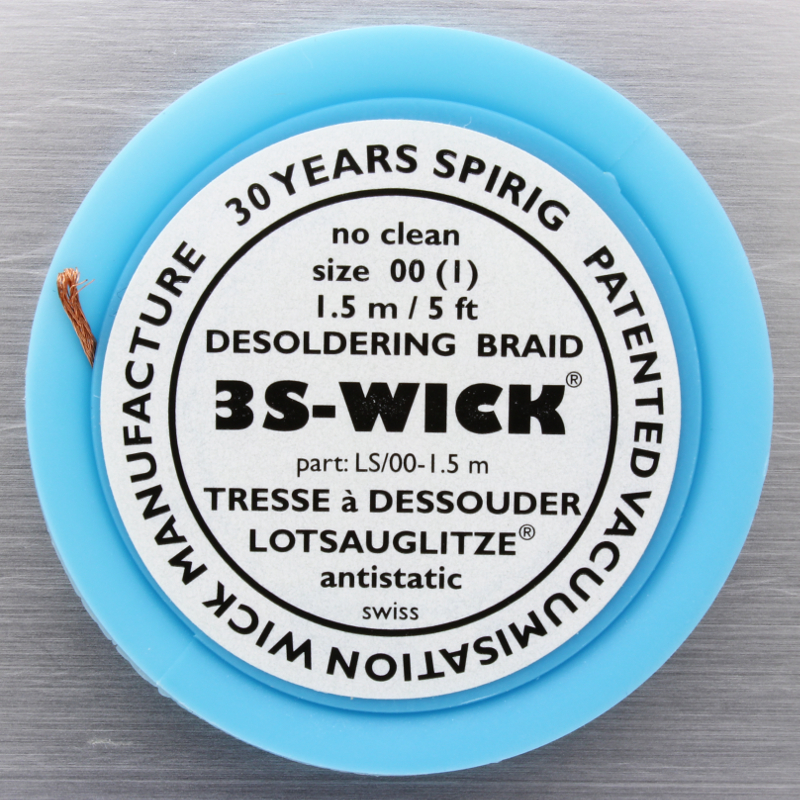
Meet the Solder Wick
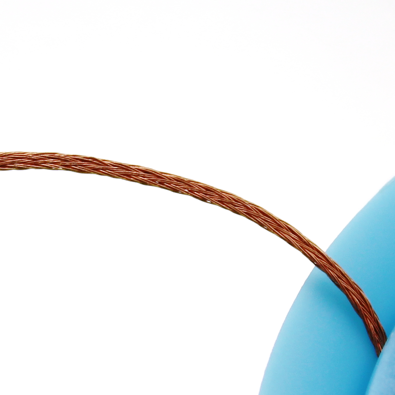
This is a very useful tool when soldering SMT components. Also known as desoldering wick or braid, the solder wick is a mesh of copper threads usually coated with rosin flux, and it’s hungry for solder!
When heated near the solder, it will wick it up into the braids by capillary action, thus removing any excessive solder. Keep it at hand to remove shortcircuits.
8 simple steps
The first 4 steps are about fixing the component to board in a way it will let you work with confidence. You won’t be soldering all the pins to the board in these 4 steps, but just enough pins to keep it relatively steady.
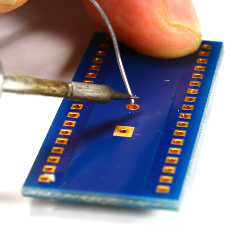
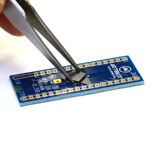
Step 1: plan ahead
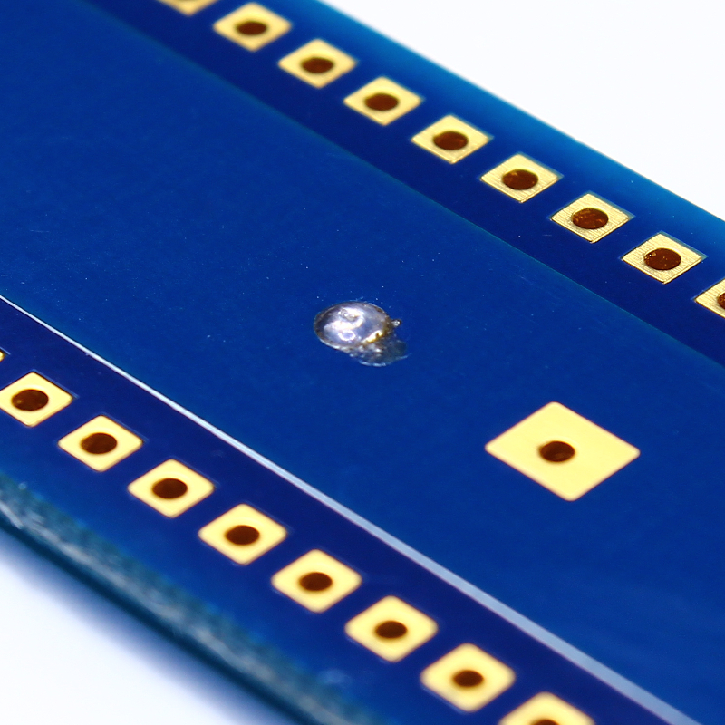
First apply some solder on any pad near the corner. As shown in the following picture, I’ve dropped some solder to the top-right one.
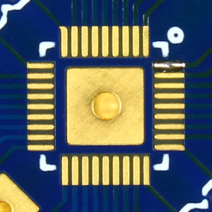
After the next step and soldering this first pad, the component will stay centered and slightly fixed, but allowing some movement in case it’s needed to correct the centering angle later.
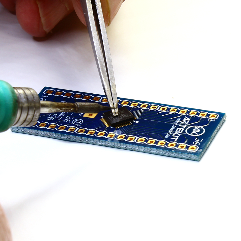
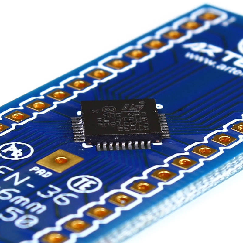
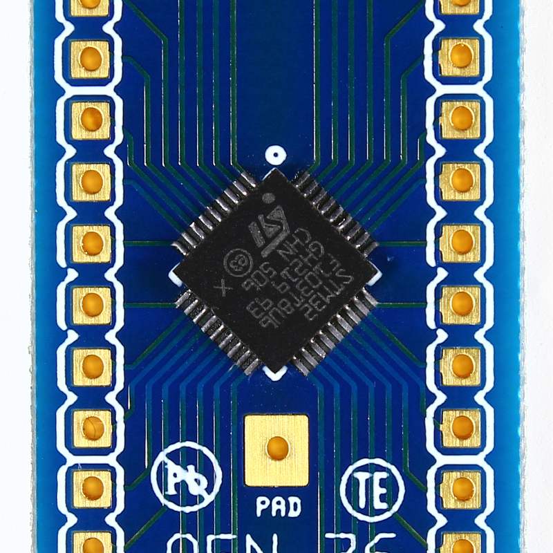
Step 2: centering the component
Using the tweezers, place and center the component on the land pattern. Use the body square (drawn with silk mask around the pattern) as a guide to center the component. This is a very important and delicate step. Do not go forward if the component is not properly centered! Use a magnifying glass lamp if needed.
Remember to align the pin 1 of the component with the pin 1 on the land pattern. This way, the pin number on the breakout board will match the pin number of the component.
Step 3: soldering the first pad
Once centered, gently open the tweezers and release the component. Check if it’s still centered, otherwise pick it up and center it again.
Once the desired position is achieved, use the tweezers to apply some pressure on the top of the component.

Solder the pad you have chosen in the Step 1, and make sure the component is still centered. If needed, heat the pad again and correct the centering of the component.
Step 4: second solder point
Solder the pad in the opposite corner of the pad you’ve chosen in Step 1. Here you can apply some little force to better center the component. Beware of not desoldering the first pad you’ve soldered!
Step 5: soldering a side
Now you should have a steady, fixed and centered component. The previous step were the most difficult; now it gets simpler.
Choose one of the two sides you have not soldered any pin yet. Apply some flux with the brush along the pads. Be generous with the flux: take into consideration that it evaporates quickly when it’s close to the soldering iron tip.
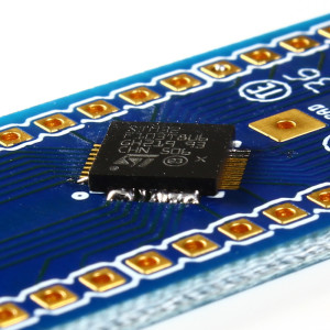
Then get some solder and using the soldering iron, pass it along the pads. Don’t worry about shortcircuits, we will clean those in the following step. Take a look at the resulting (and relatively normal) mess you could end with:
Step 6: removing shortcircuits
Now, we will use the solder wick to clean up and remove the excess solder. This will also remove any eventual shortcircuit. It also recommended to use some flux in this step, to help the solder to flow into the wick.
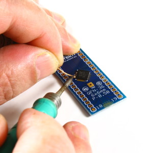
Place a clean strip of solder wick on top of the area you want to clean up. On top of the solder wick, place the soldering iron and move the wick around. If the wick gets too dirty or starts opening, it’s time to stop and cut it with diagonal pliers.
After cleaning up eventual solder excess you should have a neat and clean soldering around the pads.
Step 7: repeat
Now repeat from Step 5 and solder the remaining sides. When you’re done, admire your work.
Step 8: soldering the center pad (optional)
Some components need a ground connection to the center pad. Others need to dissipate heat through contact with the board. Often this pad is also referred as “Exposed pad” in the datasheets.
In any case, it’s recommended to solder this central pad if the IC has one. You can apply some solder to the hole on the bottom of the board. It’s convenient to drop a some flux into the hole to help the solder flow up to the component.
Now you can use the dedicated pad (named ‘PAD’ with silk screen) to connect the central pad to ground, if needed.
Conclusion
This work is really finished when you clean up the board of eventual flux and solder residues. There are some options; the simpler one involves nail polish remover and the brush you’ve used for the flux, or professional flux removers on the market.
This is the kind of work that needs a lot practice. Once you have mastered it, a whole new world of SMT components awaits to be used in your projects.