Thanks to Laurence Vanhelsuwe, of Software Pearls, for submitting this article.
One of the nit-picking criticisms the Raspberry Pi boards get, is that they do not have an on-board real-time clock. When the power is switched off, those poor Raspberries forget what time and day it is.
For network-connected Raspberry Pis, this is no big deal, since the system time and date can be obtained during the boot sequence via NTP, or similar. But if you’d like to use a Raspberry Pi model A (which has no Ethernet), and its sole USB port is used for something other than a Wifi dongle, then you are potentially faced with the lack of an on-board clock. Especially if, like myself, you’d like to make a fancy wall clock with a Raspberry Model A as the brains driving the hours and minutes display !
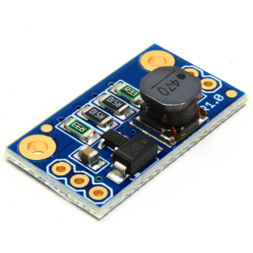
Artekit has the perfect solution: just hook up a AK-DS1307 real time clock (RTC) module to your Raspberry, and your Raspberry will never again forget what time it is, or what day of the year it is. OK, when we say “hook up”, we mean hook up and write some code… which is what we’ll do in this blog post. At the end of the article, we’ll be reading the time and date from the RTC module, and, if you need to, set the RTC time and date too.
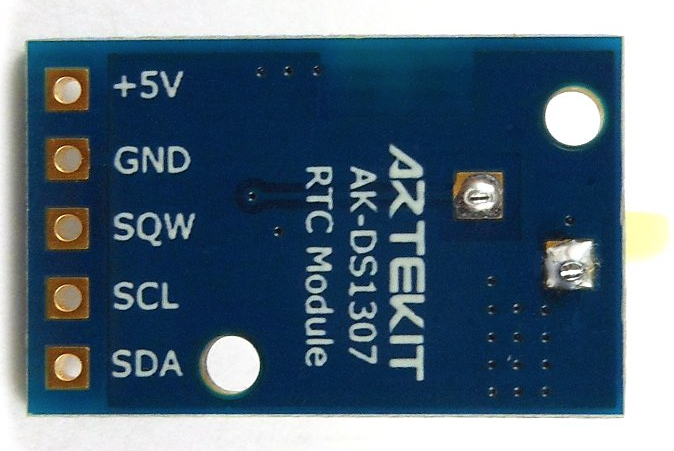
The AK-DS1307 is built around the Maxim Integrated DS1307 chip, which needs to be approached via I2C – the popular “2-wire” electronics communication bus. Below is a picture of the back of the module, showing the I2C lines SDA and SCL, along with +5V and ground (plus a fifth line, SQW standing for Square Wave, which we won’t use).
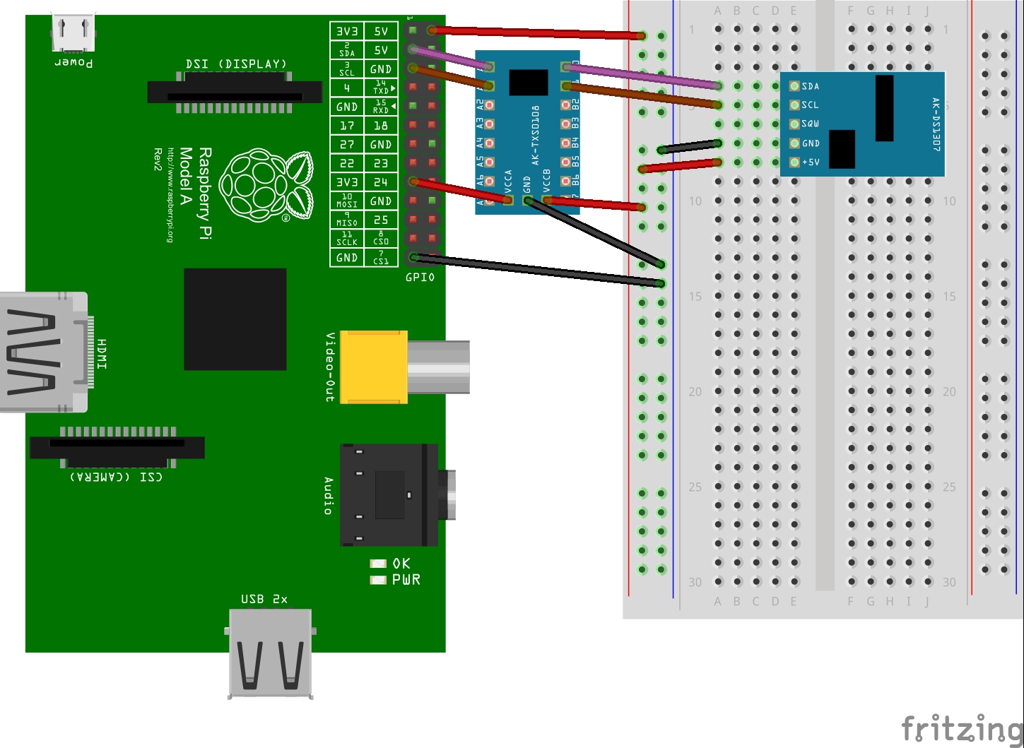
Raspberries have explicit I2C support, so wiring the RTC to the Raspberry is just a matter of connecting the four pins as the following diagram shows:
Unfortunately, I2C software support is not enabled by default on an off-the-shelf Raspberry, and it takes some configuring to rectify this. I suggest you first get that chore out of the way, by following this quick guide. Once you’ve got your I2C configuration out of the way, you should get the following output when using the i2cdetect command (with an AK-DS1307 properly connected):
pi@artekit ~ $ i2cdetect -y 1
     0  1  2  3  4  5  6  7  8  9  a  b  c  d  e  f
00:          -- -- -- -- -- -- -- -- -- -- -- -- --
10: -- -- -- -- -- -- -- -- -- -- -- -- -- -- -- --
20: -- -- -- -- -- -- -- -- -- -- -- -- -- -- -- --
30: -- -- -- -- -- -- -- -- -- -- -- UU -- -- -- --
40: -- -- -- -- -- -- -- -- -- -- -- -- -- -- -- --
50: -- -- -- -- -- -- -- -- -- -- -- -- -- -- -- --
60: -- -- -- -- -- -- -- -- 68 -- -- -- -- -- -- --
70: -- -- -- -- -- -- -- --
pi@artekit ~ $
The ‘68‘ is the magic hexadecimal number you’re looking for: it’s the I2C device ID of the AK-DS1307, and is proof that both your I2C configuration is correct, and your DS1307 is alive and well on the I2C bus.
Whenever you’re faced with an I2C device, the simplicity of the physical connection typically hides a complexity at the protocol level which is orders of magnitude greater. So it really pays to download the device data sheet, and study the details. But if you’re in a hurry, here are the guts of what the DS1307 chip is all about: a set of registers that keep track of time and date, regardless of the state of your power supply. The following is an extract from page 8 of the Maxim data sheet:
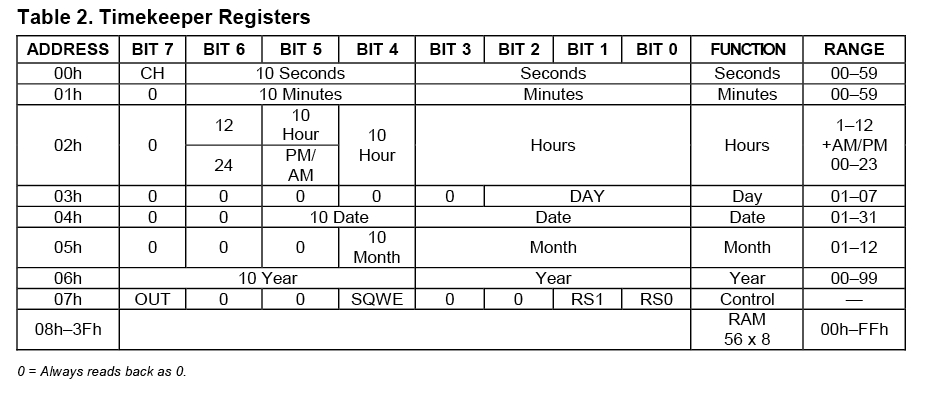
If you’re not used to deciphering such register descriptions, let’s go through this table one step at a time. First, note that each register (one row of the table) consists of a byte (8 bits) that lives at a certain address in the chip. Just like every byte of RAM has a unique address in your PC, so do I2C registers within the address space of the device, with the difference that a typical I2C device has just a few dozen registers, while your typical RAM has millions or billions of addressable bytes.
We’re in luck: the DS1307 doesn’t feature dozens of registers, it only has eight special registers (addresses 0 to 7, shown in hex as 00h to 07h in the table), of which the first 7 reflect the core functionality of the chip: keeping the time and date. These registers are a bit awkward from a modern software point of view in that they do not store integers in “normal” or everyday format (called two’s complement, to be a bit more formal), but in binary coded decimal (BCD).
BCD is an alternative integer encoding whereby each nibble (4-bit half of a byte) of a byte stores a single decimal digit (0..9). This way of storing integers makes interpreting the content of BCD registers very easy, as long as we’re displaying their content in hexadecimal. For example, the hex value $45 is just plain decimal 45, if the content is encoded in BCD (of course, if it’s in two’s complement, $45 is 69!). In the Stone Age of computing, displaying information in hex was pretty common, so BCD can be traced back to that era. Today, computer science has almost forgotten about BCD (no self-respecting modern computer language supports it). In the electronics world, on the other hand, BCD is still used because of the ease with which 7-segment displays can be driven by decade counting chips, which still stubbornly continue to use BCD.
Now that we’ve explained the basics of BCD, it is much easier to understand the above DS1307 register set table. Let’s take the seconds register (at address 0, i.e. it is the first register that can be addressed via I2C): it stores only the seconds within the current minute, so it stores 0..59, but not more (a byte can store 256 different values, so BCD is quite wasteful). The table shows that bits 4-5-6 hold the “10 Seconds” and bits 0-1-2-3 hold the “Seconds”… this is just a slightly confusing way of stating that the 0..59 seconds are simply stored in BCD format in the register.
The same applies to nearly all the other registers: minutes, hours, date, month and year are all to be encoded as BCD. The exception is the day number register at address 3: it can be stored in plain two’s complement. Actually since the valid range for the day number is 1-7, the encoding in two’s complement and BCD are exactly the same.
The next aspect of the table to note is the valid value range for each register. Take the month register (address 5): it counts months from 1 to 12, not from 0 to 11, as other systems may do. So when writing this register, we’re not allowed to store any value outside this range! The year register (address 6) is also special because it only allows 0 to 99 as valid (decimal) values, so how does it store 2014, for example? Well, it doesn’t directly, but indirectly, by assuming a base (or offset) of 2000; again, this is different from other well-known systems (Unix uses 1970, Java’s Date class uses 1900, and so on).
The hours can be counted from 0..23, or from 1..12 in AM/PM mode. We’re not going to use the AM/PM mode in this article, but if you want, the chip can be used that way too.
A final feature of the chip, which we won’t use either, is the 56 bytes of RAM starting at address 8. Feel free to hide your most secret of secrets in there.. 56 bytes is plenty of room for a pretty serious password, and I doubt many virusses are capable of finding such a hiding place.
At this stage, before we begin to consider any I2C, we’re already in a position to write a Java class which will actually be the bulk of the code presented. The class DS1307Registers is, more or less, the above table turned into Java code: a DS1307Registers object is a local copy (or proxy, if you wish) for the hardware registers in the chip. When reading from the chip, we’re going to want to initialiaze a DS1307Registers from raw bytes provided by the chip over the I2C bus, and when writing to the chip, we’re going to first set the register values in the object, and then write out the entire register set in one go. Some of you may think this is a somewhat indirect way of doing things, but actually it’s just applying standard object-oriented design to the problem at hand: you should always model the things you interact with as objects.
Here’s the code for the DS1307Registers class:
import static BCDKit.fromBCD;
import static BCDKit.toBCD;

import java.text.DateFormat;
import java.text.SimpleDateFormat;
import java.util.Date;

/************************************************************************
* The register set of a Maxim Integrated DS1307 Real-Time Clock (RTC) chip.
* This class is independent of any I2C code.
************************************************************************/
public class DS1307Registers {

    private static final int MAX_SECONDS = 59;
    private static final int MAX_MINUTES = 59;

    private static final int MIN_DAY_NUMBER = 1;
    private static final int MAX_DAY_NUMBER = 7;

    private static final int MIN_DATE = 1;
    private static final int MAX_DATE = 31;

    private static final int MIN_MONTH = 1;
    private static final int MAX_MONTH = 12;

    private static final int MAX_YEAR = 99;
    private final static byte AMPM_MASK = 0x40;

    private byte bcdSeconds; // 00.59
    private byte bcdMinutes; // 00..59
    private byte bcdHours; // 00..23 (01..12 in AM/PM mode)
    private byte dayNumber; // 01.07
    private byte bcdDate; // 01..31
    private byte bcdMonth; // 01..12
    private byte bcdYear; // 00..99
    private byte controlByte;

    /**
    * Default constructor. All registers set to defaults.
    */
    public DS1307Registers() {

        dayNumber = bcdDate = bcdMonth = 1;
    }

    /**
    * Copy the first 8 bytes of the argument byte array into the registers.
    *
    * @param bytes
    */
    public void setRegisters(final byte[] bytes) {

        if (bytes.length < 8) {
            throw new IllegalArgumentException("Byte array length too short (needs to be at least 8): " + bytes.length);
        }

        int i = 0;

        bcdSeconds = bytes[i++];
        validate("Seconds", "have", getSeconds(), 0, MAX_SECONDS);

        bcdMinutes = bytes[i++];
        validate("Minutes", "have", getMinutes(), 0, MAX_MINUTES);

        bcdHours = bytes[i++];

        dayNumber = bytes[i++];
        validate("Day number", "has", getDayNumber(), MIN_DAY_NUMBER, MAX_DAY_NUMBER);

        bcdDate = bytes[i++];
        validate("Date", "has", getDate(), MIN_DATE, MAX_DATE);

        bcdMonth = bytes[i++];
        validate("Month", "has", getMonth(), MIN_MONTH, MAX_MONTH);

        bcdYear = bytes[i++];
        validate("Year", "has", getYear(), 0, MAX_YEAR);

        controlByte = bytes[i++];
    }

    private void validate(final String name, final String hasHave, final int value, final int min, final int max) {

        if ((value < min) || (value > max)) {
            throw new IllegalArgumentException(name + " " + hasHave + " to be in [" + min + ".." + max + "] range. Illegal: " + value);
        }
    }

    /**
    * Get the register set as a raw byte array.
    *
    * @return a byte[8]
    */
    public byte[] asByteArray() {

        final byte[] bytes = new byte[8];
        bytes[0] = bcdSeconds;
        bytes[1] = bcdMinutes;
        bytes[2] = bcdHours;
        bytes[3] = dayNumber;
        bytes[4] = bcdDate;
        bytes[5] = bcdMonth;
        bytes[6] = bcdYear;
        bytes[7] = controlByte;

        return bytes;
    }

    public int getSeconds() {
        return fromBCD(bcdSeconds);
    }

    public void setSeconds(final int seconds) {
        bcdSeconds = toBCD(seconds);
    }

    public int getMinutes() {
        return fromBCD(bcdMinutes);
    }

    public void setMinutes(final int minutes) {
        bcdMinutes = toBCD(minutes);
    }

    public int getHours() {
        return fromBCD(bcdHours);
    }

    public void setHours(final int hours) {
        bcdHours = toBCD(hours);
    }

    public boolean isAMPMMode() {
        return (bcdHours & AMPM_MASK) != 0;
    }

    /**
    * Get the day number (1..7, representing Mon..Sun)
    *
    * @return the day number
    */
    public int getDayNumber() {
        return dayNumber;
    }

    public void setDayNumber(final int dayNumber) {
        this.dayNumber = (byte) dayNumber;
    }

    public int getDate() {
        return fromBCD(bcdDate);
    }

    public void setDate(final int date) {
        bcdDate = toBCD(date);
    }

    public int getMonth() {
        return fromBCD(bcdMonth);
    }

    public void setMonth(final int month) {
        bcdMonth = toBCD(month);
    }

    /**
    * Get the 2-digit year. I.e. 2014 is returned as 14.
    *
    * @return the year
    */
    public int getYear() {
        return fromBCD(bcdYear);
    }

    public void setYear(final int year) {
        bcdYear = toBCD(year);
    }

    public byte getControlByte() {
        return controlByte;
    }

    /**
    * Set the registers to reflect the given Date.
    *
    * @param date
    */
    @SuppressWarnings("deprecation")
    public void set(final Date date) {
        final int seconds = date.getSeconds();
        final int minutes = date.getMinutes();
        final int hours = date.getHours();

        final int day = date.getDate();
        final int month = date.getMonth();
        final int year = date.getYear();

        setSeconds(seconds);
        setMinutes(minutes);
        setHours(hours);

        setDate(day);
        setMonth(month + 1);
        setYear(year - 100);
    }

    public String asPrettyString() {
        final DateFormat format = new SimpleDateFormat("dd/MM/yyyy HH:mm:ss z");
        return formattedBy(format);
    }

    public String formattedBy(final DateFormat dateFormat) {
        final Date date = new D ate(100 + getYear(), getMonth() - 1, getDate(), getHours(), getMinutes(), getSeconds());
        return dateFormat.format(date);
    }

    @Override
    public String toString() {
        return "DS1307[" + //
                        hex(bcdSeconds) + hex(bcdMinutes) + hex(bcdHours) + "-" + //
                        hex(dayNumber) + "-" + //
                        hex(bcdDate) + hex(bcdMonth) + hex(bcdYear) + "-" + //
                        hex(controlByte) + //
                        "]";
    }

    private static String hex(final int byteValue) {
        return Integer.toHexString(byteValue | 0x80000000).substring(6, 8).toUpperCase();
    }

    public static void main(final String[] args) {

        final DS1307Registers ds1307Registers = new DS1307Registers();
        final byte[][] registerSetSamples = {
            new byte[] {
                0, 0, 0, 1, 1, 1, 0, 0
            }, new byte[] {
                0x00, 0x30, 0x14, 1, 0x02, 0x11, 0x14, 0
            }, new byte[] {
                0x59, 0x59, 0x23, 1, 0x31, 0x12, 0x79, 0
            }
        };

        for (final byte[] registerSetSample : registerSetSamples) {
            ds1307Registers.setRegisters(registerSetSample);
            System.out.println(ds1307Registers + " = " + ds1307Registers.asPrettyString());
        }
    }
}
Although the class is nearly 300 lines of code, its structure can be broken down to the following, individually simple, aspects:
The class also deliberately does not concern itself with I2C. In the next section we’re going to tackle the I2C requirements, but from a Raspberry Pi perspective. Since the DS1307Registers class does not deal with I2C, it could be reused on other (Java-compatible) platforms such as other single-board computers, provided the I2C handling is done the way such other platform demands.
Here’s the code for the BCDKit class used by our registers class:
/**
 * Kit of [B]inary [C]ode [D]ecimal routines.
 */
public final class BCDKit {
    private BCDKit() {
    }

    /**
     * Converts a 2-digit integer (0..99) to BCD.
     *
     * @param an integer in the range 0..99
     */
    public static byte toBCD(final int n) {
        return (byte) ((n / 10 * 16) + (n % 10));
    }

    /**
     * Converts a value from BCD to plain integer.
     *
     * @param bcdByte a byte holding a BCD-encoded value (in range 0..99)
     */
    public static byte fromBCD(final int bcdByte) {
        final int b = bcdByte & 0xFF;
        return (byte) ((b / 16 * 10) + (b % 16));
    }
}
Now that we’ve introduced the RTC chip’s register structure, it’s time to read or write those registers, using I2C.
If you haven’t used an I2C device before, the essence of I2C can be summarized using two acronyms: SDA and SCL. Data and Clock. These two lines, plus Vcc and ground, are all you need to hook up any I2C device to a master such as a Raspberry Pi.
As with the article on how to drive AK-Mr.Wood-L displays, we’re going to use the Pi4J library to make our life much easier when it comes to I2C communications (if you haven’t installed the library on your Pi yet, please refer to the library’s official site for installation instructions).
Some of the effort that the Pi4J library saves us can be gleaned from the following top-level class used to continually display the contents of the DS1307 in pretty-printed human-readable form:
import com.pi4j.io.i2c.I2CBus;
import com.pi4j.io.i2c.I2CDevice;
import com.pi4j.io.i2c.I2CFactory;
import java.io.IOException;

/**
 * Read the time of an I2C-connected DS1307 Real-Time Clock chip.
 */
public final class ReadDS1307Time {
    private static final int DEVICE_ID = 0x68;

    public static void main(final String[] args) throws IOException {

        final I2CBus i2cBus = I2CFactory.getInstance(I2CBus.BUS_1);
        final I2CDevice device = i2cBus.getDevice(DEVICE_ID);
        final DS1307 rtc = new DS1307(device);

        while (true) {
            rtc.readClock();
            System.out.println(rtc);
        }
    }
}
This diminutive program contains all of the boilerplate I2C code needed to approach any I2C device connected to a Raspberry Pi:
Note that selecting a device is a pure Pi4J library concept; nothing happens at the I2C protocol level when such a statement executes.
Our ReadDS1307Time class is kept as brief as possible through the use of our next class, DS1307, which you can think of as a combination of our DS1307Registers class with some Pi4J calls:
import com.pi4j.io.i2c.I2CDevice;
import java.io.IOException;
import java.util.Date;

/**
 * I2C-connected DS1307 Real-Time Clock chip.
 */
public final class DS1307 extends DS1307Registers {

    private static final int RTC_STRUCT_SIZE = 8;
    private static final byte[] RTC_STRUCT = new byte[RTC_STRUCT_SIZE];
    private final I2CDevice rtc;

    /**
     * Constructor.
     *
     * @param rtc an I2CDevice pointing to a DS1307
     */
    public DS1307(final I2CDevice rtc) {
        this.rtc = rtc;
    }

    /**
     * Read the clock into our local register copies.
     *
     * @throws IOException
     */

    public void readClock() throws IOException {
        rtc.read(0, RTC_STRUCT, 0, RTC_STRUCT_SIZE);
        setRegisters(RTC_STRUCT);
    }

    /**
     * Write the given Date out to the RTC registers.
     *
     * @param date
     * @throws IOException
     */

    public void writeClock(final Date date) throws IOException {
        set(date);
        final byte[] rawRegisterBytes = asByteArray();
        rtc.write(0, rawRegisterBytes, 0, RTC_STRUCT_SIZE);
    }
}
The DS1307 class is similar to the DS1307Registers class in that, as any good object-oriented class, it is a reflection of the actual thing it is modelling, and exposes a concise set of methods reflecting the physical device’s functions.
As promised at the start of the article, we can now run the code, and see the RTC in action.
pi@artekit ~ $ sudo java -cp all.jar ReadDS1307Time
This should produce console output like the following:
01/11/2014 14:39:09 UTC
01/11/2014 14:39:10 UTC
01/11/2014 14:39:10 UTC
01/11/2014 14:39:10 UTC
01/11/2014 14:39:11 UTC
01/11/2014 14:39:11 UTC
01/11/2014 14:39:11 UTC
01/11/2014 14:39:11 UTC
If the time and/or date in your AK-DS1307 isn’t correct, you can also run the following program, which sets the time and date to reflect the Raspberry’s system time (so if you are running this on a Raspberry Pi which hasn’t had its time/date set yet, you need to do this manually first, using the Linux date -s command).
import com.pi4j.io.i2c.I2CBus;
import com.pi4j.io.i2c.I2CDevice;
import com.pi4j.io.i2c.I2CFactory;
import java.io.IOException;
import java.util.Date;

/**
 * Write the system time to a I2C-connected DS1307 Real-Time Clock chip.
 */

public final class WriteSystemTimeToDS1307 {

    private static final int DEVICE_ID = 0x68;

    public static void main(final String[] args) throws IOException {
        final I2CBus i2cBus = I2CFactory.getInstance(I2CBus.BUS_1);
        final I2CDevice device = i2cBus.getDevice(DEVICE_ID);
        final DS1307 rtc = new DS1307(device);

        final Date now = new Date();

        rtc.writeClock(now);

        rtc.readClock();

        System.out.println(rtc.asPrettyString());
    }
}
It takes little effort to use the AK-DS1307, both from an electronics point of view, and from a software point of view. As with all I2C devices, the most effort goes into reading the data sheet and understanding how the device’s internal data structures, or registers, are meant to be exploited. In the case of the DS1307 chip, the main labour-intensive aspect is dealing with the BCD encoding/decoding demanded by the chip design.
Click here to download all the source code.